Bosch Conettix D6600 Installation And Operation Manual
Communications receiver/gateway
Hide thumbs
Also See for Conettix D6600:
- Manual (185 pages) ,
- Installation and operation manual (88 pages) ,
- Operation and installation manual (36 pages)

Related Manuals for Bosch Conettix D6600


Summary of Contents for Bosch Conettix D6600
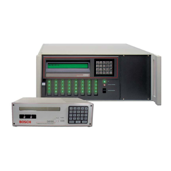
- Page 1 Conettix D6600/D6100i Installation and Operation Guide Communications Receiver/Gateway...
-
Page 2: Table Of Contents
EN | 2 Conettix D6600/D6100i | Installation and Operation Guide | Introduction Contents Introduction ..........3 10.1.5 How Call Groups Work....... 15 Emergency Procedures ......4 10.1.6 Buzzer Operation ........16 Card Functions and Locations....4 10.1.7 Reporting Devices: Primary and Secondary16 D6600 ............4 10.2... -
Page 3: Introduction
Conettix D6600/D6100i | Installation and Operation Guide | 1.0 Introduction Up to seven additional telephone line cards along with Trademarks seven additional line terminator cards can be installed in the D6600 to expand the receiver’s capacity to 32 ® ®... -
Page 4: Emergency Procedures
Conettix D6600/D6100i | Installation and Operation Guide | 2.0 Emergency Procedures 2.0 Emergency Procedures 3.0 Card Functions and Locations Section17.0 Service Information on page 34 of this guide contains a Service Information form. Keep this D6600 form current and accessible to central station personnel at all times in case of emergency. -
Page 5: Line Cards And Modules
Conettix D6600/D6100i | Installation and Operation Guide | 3.0 Card Functions and Locations 3.1.2 Line Cards and Modules Table 4: D6600 Line Cards and Modules Table 2: Power LED Indications Name Model Description Present Power LED Status Telephone D6640 Up to eight line cards can be... -
Page 6: Rear View
Conettix D6600/D6100i | Installation and Operation Guide | 3.0 Card Functions and Locations 3.1.3 Rear View The D6600 has input and output pin connector sockets for up to eight line cards, network option (if installed), and one CPU card. It also has slots for connecting these cards to their corresponding terminator cards. -
Page 7: Front Panel
Conettix D6600/D6100i | Installation and Operation Guide | 4.0 D6600 Specific Cards 4.0 D6600 Specific Cards D6100i 3.2.1 Front Panel D6640/D6641 Line Cards and D6645 Line Terminator Card Figure 4: D6100i Communications Receiver/ Gateway (Front View) Figure 6: D6640/D6641 Line Card 1 –... -
Page 8: D6640/D6641 Led Descriptions
Conettix D6600/D6100i | Installation and Operation Guide | 4.0 D6600 Specific Cards 4.1.1 D6640/D6641 LED Descriptions 4.1.2 Card Installation The LED is active until the system acknowledges the Discharge static electricity from your entire transmission and the telephone line is ready to body by touching the receiver’s internal... -
Page 9: D6640/D6641Telephone Line Monitoring Voltage
Conettix D6600/D6100i | Installation and Operation Guide | 4.0 D6600 Specific Cards D6610 CPU Card and D6615 CPU Figure 9: Removing and Installing the Terminator Card Terminator Card 4.2.1 D6610 CPU Card Connection The CPU card connects to the user interface on the front of the D6600 using a 50-pin ribbon cable socket. -
Page 10: Card Removal And Replacement
Conettix D6600/D6100i | Installation and Operation Guide | 5.0 Power Supply Modules (D6600 Only) Parallel printer connection: Use the DB25 port on 4.2.3 Card Removal and Replacement the back of the D6600/D6100i rear panel to connect Remove power to the D6600 before to a standard parallel text printer. -
Page 11: Rack Mount Instructions
Conettix D6600/D6100i | Installation and Operation Guide | 8.0 Power 10. Turn the D6600 power switch on. The D6100i Power starts as soon as you plug in the AC Transformer. 11. Set the calendar and clock to the correct date and Main Power time and program the necessary options. -
Page 12: Minimum Standby Battery
Conettix D6600/D6100i | Installation and Operation Guide | 8.0 Power Table 6: Calculating Standby Current for the D6600 Device 12 V Battery Standby UPS AC Standby Current Current D6600 (one D6640/ D6641/D6645 800 mA 800 mA 350 mA 350 mA... -
Page 13: Input And Output Ports
Conettix D6600/D6100i | Installation and Operation Guide | 9.0 Input and Output Ports 9.0 Input and Output Ports UPS Monitoring through CPU Programmable Input Ports Refer to the appropriate Installation Use the CPU programmable input port to connect the Supplement included with your product... -
Page 14: Input Reverse Connection Configuration
Conettix D6600/D6100i | Installation and Operation Guide | 9.0 Input and Output Ports Automation Link Monitoring 9.1.2 Input Reverse Connection Configuration (COM3) through CPU If the input must be the opposite polarity for correct operation, place an external transistor circuit between... -
Page 15: D6600/D6100I Operation
Conettix D6600/D6100i | Installation and Operation Guide | 10.0 D6600/D6100i Operation 10.0 D6600/D6100i Operation Some communicators wait approximately 30 sec for the proper handshake tone. 10.1 Process Flow Others hang up immediately if they hear an improper handshake tone. Others 10.1.1 Receiver Handshake and Kiss-Off... -
Page 16: Buzzer Operation
Conettix D6600/D6100i | Installation and Operation Guide | 10.0 D6600/D6100i Operation 10.2 Normal Operation Mode 10.1.6 Buzzer Operation In the Manual Mode, an Operator Alert Buzzer In Normal Operation Mode, the D6600/D6100i sends sounds when a message is received until you press messages immediately or in blocks to reporting the [ACKNOWLEDGE] key. -
Page 17: Operating In Manual Mode
Conettix D6600/D6100i | Installation and Operation Guide | 10.0 D6600/D6100i Operation 10.3 Operating in Manual Mode 10.4 Keypad Menu Operation If all reporting devices (such as printers and 10.4.1 Log In computers) fail, the D6600/D6100i reverts to Manual Mode until a device returns to service. -
Page 18: Event Buffer Display
Conettix D6600/D6100i | Installation and Operation Guide | 10.0 D6600/D6100i Operation 10.4.3 Event Buffer Display 10.4.4 Current System Trouble Display D6600 D6100i D6600 Shows event buffer contents SYST EM TROUBLE in the order the events are System troubles in the... -
Page 19: Keypad Functions
Conettix D6600/D6100i | Installation and Operation Guide | 10.0 D6600/D6100i Operation 10.4.6 Keypad Functions 10.4.7 Skip Current Automation Event Use this option to test the communication links to the Use this option to skip the current Automation event. automation firmware and printer. -
Page 20: Line Test
Conettix D6600/D6100i | Installation and Operation Guide | 10.0 D6600/D6100i Operation 10.4.8 Line Test 10.4.9 Clear Pending Events Use this option to test the line operation. Use this option to clear all pending events. D6600 D6100i D6600 D6100i FUNCTION FUNCTION Enter password. -
Page 21: Busy Seconds (Line Busy) Reports
Conettix D6600/D6100i | Installation and Operation Guide | 10.0 D6600/D6100i Operation 10.5 Busy Seconds (Line Busy) Reports D6600 D6100i The D6600/D6100i monitors and reports when a call ENTER group of receiver lines cannot receive signals. The receiver cannot process signals if its incoming telephone lines are in trouble, if other communicators have the line tied up, or if the line card is inoperative. -
Page 22: Two-Way Audio
Conettix D6600/D6100i | Installation and Operation Guide | 10.0 D6600/D6100i Operation 10.6 Two-Way Audio When the Hold option is set for 1 to 99 sec, the line card remains off-hook for the programmed hold after When using the D6600/D6100i for Two-Way Audio... -
Page 23: Two-Way Audio Modes Of Operation
Conettix D6600/D6100i | Installation and Operation Guide | 10.0 D6600/D6100i Operation 10.6.2 Two-Way Audio Modes of Operation • Transfer: D6600/D6100i transfers the incoming line to another line; a flash operation occurs at the end of the alarm signal. The receiver dials the line programmed at Transfer Phone Number (refer to Menu Items 3.1.4.18 Flash [x 100ms] and... -
Page 24: Network Communications
Conettix D6600/D6100i | Installation and Operation Guide | 11.0 Network Communications 11.0 Network Communications Figure 14: Conettix Network System Connection Diagram - C900TTL- References to the Network Ethernet E/C900V2 and Any Control Panel Module model number are defined in the Installation Supplement. -
Page 25: No Data Received Reports
Conettix D6600/D6100i | Installation and Operation Guide | 12.0 No Data Received Reports 12.0 No Data Received Figure 15: Conettix Network System Connection Diagram - Reports D9133TTL-E/DX4020 and Bosch Control Panels 12.1 Description If a message is garbled (incorrect checksum or... -
Page 26: Central Station Automation System
Conettix D6600/D6100i | Installation and Operation Guide | 13.0 Central Station Automation System 13.0 Central Station Figure 17: Receiver System – Direct Connect Automation System If using a Bosch Security Systems, Inc. receiver, connect a central station automation system computer to the COM3 port (automation computer port) on the rear of the receiver with a null-modem cable. -
Page 27: Central Station Tips
Conettix D6600/D6100i | Installation and Operation Guide | 14.0 Central Station Tips 14.0 Central Station Tips Figure 18: Receiver System – Standard/Network Automation 14.1 Back-up Receiver Spare circuit boards and receivers should be available at the central station. Keep a spare kit on hand. -
Page 28: Proper Ground
Conettix D6600/D6100i | Installation and Operation Guide | 14.0 Central Station Tips 14.5 Proper Ground Connect the receivers to an earth ground, not a chassis or electrical ground. Measure the resistance of the receiver ground to another ground. If the meter reads above 2 Ω, check your receiver ground against... -
Page 29: Troubleshooting Guide
Section 3.0 Card Functions and Locations on page 4). Do not attempt to repair individual assemblies. Return any failed assemblies to Bosch Security Systems, Inc. for testing and repair. Use this Troubleshooting Guide to identify failed modular components. - Page 30 Conettix D6600/D6100i | Installation and Operation Guide | 15.0 Troubleshooting Guide Table 11: Hardware Troubleshooting Guide (continued) Symptom Problem Solution • • Operator alert System stalled Check the watchdog LED on the inside of the door behind buzzer cannot be the keypad.
- Page 31 Conettix D6600/D6100i | Installation and Operation Guide | 15.0 Troubleshooting Guide Table 11: Hardware Troubleshooting Guide (continued) Symptom Problem Solution • D6200 cannot D6200 network connection is Ensure that the Ethernet connection light on the network connect to the defective, missing, or has interface module for the PC running D6200 Software is on.
-
Page 32: Specifications
Consult the dealer or an experienced radio/TV technician for help. Any modifications made to this device that are not approved by Bosch Security Systems, Inc. may void the authority granted to the user by the FCC to operate this equipment. - Page 33 Conettix D6600/D6100i | Installation and Operation Guide | 16.0 Specifications Table 12: D6600/D6100i Specifications (continued) Industry Canada D6600 1249A-8925A D6100i 1249A-6100 This product meets the applicable Industry Canada technical specifications. The Ringer Equivalence Number is an indication of the maximum number of devices allowed to be connected to a telephone interface.
-
Page 34: Service Information
17.0 Service Information (EMERGENCY DATA SHEET) In a central station emergency, use this information to contact the necessary people and enable Bosch Security Systems, Inc. Customer Service Personnel to help you with your emergency. Ask your supervisor to provide the following information: Supervisor’s Name:... - Page 35 Conettix D6600/D6100i | Installation and Operation Guide | 17.0 Service Information Notes Bosch Security Systems, Inc. | 6/09 | 4998122704-06...
- Page 36 Bosch Security Systems, Inc. 130 Perinton Parkway Fairport, NY 14450-9199 (800) 289-0096 © 2009 Bosch Security Systems, Inc. 4998122704-06...
Need help?
Do you have a question about the Conettix D6600 and is the answer not in the manual?
Questions and answers