Table of Contents
Advertisement
Quick Links
Advertisement
Table of Contents

Related Manuals for Bosch FWI‑270


Summary of Contents for Bosch FWI‑270
- Page 1 Radio gateway FWI‑270 Operation Manual...
-
Page 3: Table Of Contents
Replacing the radio gateway FWI-270 Basic principles for replacing the battery pack Replacing the battery pack on the radio gateway Specifications Technical data Dimensions Master gauge for recesses Environmental compatibility and disposal Bosch Sicherheitssysteme GmbH Operation Manual 2019.10 | 2.0 | F.01U.373.488... -
Page 4: About This Document
Intended use The radio gateway and its specified radio devices form a wireless fire detection system. The radio gateway is intended for use with Bosch fire alarm detection systems. Other applications are not permitted. Technical terms and abbreviations... -
Page 5: Safety
CAUTION identifies a dangerous situation, which could result in slight to moderately serious injury if you do not avoid this situation. NOTICE NOTICE identifies possible damage to property that may result from non-observance. Bosch Sicherheitssysteme GmbH Operation Manual 2019.10 | 2.0 | F.01U.373.488... -
Page 6: Safety Regulations For The Method Of Operation
Safety regulations for the method of operation National standards, regulations and legislation Bosch products are developed and produced in compliance with the relevant European and international safety standards. Should additional national or local safety standards or legislation concerning the planning, mounting, installation, operation or disposal of the product apply at the place of operation, then these must also be taken into account together with the safety regulations in the product documentation. - Page 7 Modifications to the system design and the products Modifications to the system and to individual products may lead to faults, malfunctioning and safety risks. Written confirmation must be obtained from Bosch and the corresponding safety bodies for modifications or additions.
-
Page 8: General Safety Instructions
Disregard of the safety regulations Before they are delivered, Bosch products are tested to ensure they function correctly when used properly. Bosch disclaims all liability for damage or injuries caused by the incorrect application of the instructions or the disregard of danger warnings contained in the documentation. -
Page 9: Structure And Function
Radio manual call point FDM275-O The following diagram shows possible ways of integrating the radio gateway into the fire detection system on a LSN line. Figure 3.1: FWI-270 on a LSN loop Bosch Sicherheitssysteme GmbH Operation Manual 2019.10 | 2.0 | F.01U.373.488... -
Page 10: External View
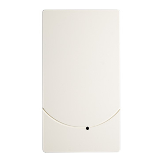
Radio manual call point FDM273-O, FDM275-O 3.1.2 External view Figure 3.2: External view of FWI-270 Screw (Torx T7) Unlocking for housing cover Opening direction LED (green) for status 3.1.3 Internal view 2019.10 | 2.0 | F.01U.373.488 Operation Manual Bosch Sicherheitssysteme GmbH... -
Page 11: Scope Of Delivery
Reset button Battery cable Battery pack Holder for battery pack 3.1.4 Scope of delivery – 1x radio gateway FWI-270 – 1x screw for cover (Torx T7) – 2x terminal block Bosch Sicherheitssysteme GmbH Operation Manual 2019.10 | 2.0 | F.01U.373.488... -
Page 12: Function
The status is displayed directly on the radio gateway by means of LEDs. External indicator, green (H1) Three indicators in the housing (H2, H3 , H4). You can see these if you open the housing cover. 2019.10 | 2.0 | F.01U.373.488 Operation Manual Bosch Sicherheitssysteme GmbH... - Page 13 H1 flashes Diagnostic Tool sets the localization green twice bit. a second H2 flashes The radio cell is in maintenance yellow once mode. a second Bosch Sicherheitssysteme GmbH Operation Manual 2019.10 | 2.0 | F.01U.373.488...
-
Page 14: Power Supply
If the LSN AUX line is temporarily switched off When the battery is full, the operating life is around one week if no power is supplied via the LSN AUX line. Accessories 3.4.1 Battery pack BAT3.6-10 2019.10 | 2.0 | F.01U.373.488 Operation Manual Bosch Sicherheitssysteme GmbH... -
Page 15: Mcl-Usb (Radio) Adapter Fduz227
Interface converter for USB on MC link – Compatible with: – Radio gateway FWI-270 – Radio manual call point FDM273-O, FDM275-O – Radio fire detector FDOOT271-O – Order number: FDUZ227 Bosch Sicherheitssysteme GmbH Operation Manual 2019.10 | 2.0 | F.01U.373.488... -
Page 16: Planning
FWI-270 as first element Overview of the radio gateway and radio devices shown in the table below: Radio device FWI-270 Radio Gateway Order number: FWI-270 FDOOT271-O Radio fire detector Order number: FDOOT271-O 2019.10 | 2.0 | F.01U.373.488 Operation Manual Bosch Sicherheitssysteme GmbH... -
Page 17: Planning Specifications
The planning specifications of your system manufacturer remain unchanged. Please observe the documentation from your system manufacturer. Network size Up to 30 radio devices may be connected to each radio gateway. Bosch Sicherheitssysteme GmbH Operation Manual 2019.10 | 2.0 | F.01U.373.488... - Page 18 Figure 4.3: Radio gateways and radio devices in a multi-story building without intermediate walls Network density Each radio device can have multiple connections to its surrounding neighbors. The distance to the surrounding neighbors must be at least 1.5 m. 2019.10 | 2.0 | F.01U.373.488 Operation Manual Bosch Sicherheitssysteme GmbH...
-
Page 19: Planning A Radio Cell
Completely different routes; i.e., different radio links and different radio devices – Radio devices connect to one another and configure themselves of their own accord. The network continuously modifies itself during operation Figure 4.4: Different paths Bosch Sicherheitssysteme GmbH Operation Manual 2019.10 | 2.0 | F.01U.373.488... - Page 20 A radio connection between a radio gateway and a radio device must take place over a maximum of three hops. 1 hop 2 hops 3 hops Radio device (hop) Radio gateway Radio link 2019.10 | 2.0 | F.01U.373.488 Operation Manual Bosch Sicherheitssysteme GmbH...
- Page 21 – Areas without fire detectors, e.g., elevator shafts, wet rooms Areas with wired fire detectors – Walls made out of metal, extremely solid concrete walls, or damp masonry Planning example: Bosch Sicherheitssysteme GmbH Operation Manual 2019.10 | 2.0 | F.01U.373.488...
- Page 22 Using a different color again, mark all the radio devices that are within the ranges of those radio devices you have already marked. If a radio link passes through two walls (exclusion zone), an additional radio device must be included in the range plans. 2019.10 | 2.0 | F.01U.373.488 Operation Manual Bosch Sicherheitssysteme GmbH...
- Page 23 Now mark the radio devices in accordance with the permissible ranges. You must look at the individual radio links from a cross-story perspective. Floor +2 40 m Floor +1 80 m Floor 0 120 m Bosch Sicherheitssysteme GmbH Operation Manual 2019.10 | 2.0 | F.01U.373.488...
- Page 24 Do not combine existing wired point detectors in the corridor with radio cells in rooms. The distances between the radio devices are otherwise increased and additional walls make communication difficult in the radio cell. 2019.10 | 2.0 | F.01U.373.488 Operation Manual Bosch Sicherheitssysteme GmbH...
- Page 25 Elevators can have a negative effect on the function of the radio cell if they are located on the same floor as the radio cell. Bosch Sicherheitssysteme GmbH Operation Manual 2019.10 | 2.0 | F.01U.373.488...
-
Page 26: Mounting /Installation
In the back box (6), break out the plastic for the cable entry: - Openings in the supporting surface for flush-mounted cables (5a) - Openings in the narrow side for surface-mounted cables (5b) Insert the cables into the back box (6). 2019.10 | 2.0 | F.01U.373.488 Operation Manual Bosch Sicherheitssysteme GmbH... - Page 27 For opening the housing, the above steps are carried out in reverse order. Terminal connection a1 / a2 LSN a1, incoming / LSN a2, outgoing LSN b1, incoming LSN b2, outgoing Shield Shielding connection Bosch Sicherheitssysteme GmbH Operation Manual 2019.10 | 2.0 | F.01U.373.488...
-
Page 28: Connecting The Radio Gateway
The radio cell can be setup in the battery mode as shown in following graphic or can be set up by using the auxiliary power (LSN AUX) or BCM (24V). 2019.10 | 2.0 | F.01U.373.488 Operation Manual Bosch Sicherheitssysteme GmbH... - Page 29 Radio gateway Mounting /Installation | en FWI-270 FWI-270 FWI-270 Figure 5.1: Connecting the radio cell to the LSN line and auxiliary power supply Bosch Sicherheitssysteme GmbH Operation Manual 2019.10 | 2.0 | F.01U.373.488...
-
Page 30: Commissioning
Working outwards from the radio gateway, commission the individual radio devices one after the other. The graphic below serves as an example of the correct sequence for commissioning radio devices. Figure 6.1: Example: Correct sequence for commissioning radio devices Radio gateway Radio device 2019.10 | 2.0 | F.01U.373.488 Operation Manual Bosch Sicherheitssysteme GmbH... -
Page 31: Commissioning The Radio Cell
To ensure that radio devices are integrated into the correct radio gateway, only one radio gateway may be in maintenance mode at any given time. Figure 6.2: Radio gateway FWI-270 Bosch Sicherheitssysteme GmbH Operation Manual 2019.10 | 2.0 | F.01U.373.488... - Page 32 If the logon process has not been successful after a long period of time has passed, briefly remove the radio device from the base/housing and then re-insert it. The search for the radio network starts again. 2019.10 | 2.0 | F.01U.373.488 Operation Manual Bosch Sicherheitssysteme GmbH...
- Page 33 Wait for the fire panel to restart. The radio cell is commissioned Refer to – Basic rules for commissioning, page 30 – Replacing the battery pack on the radio gateway, page 44 Bosch Sicherheitssysteme GmbH Operation Manual 2019.10 | 2.0 | F.01U.373.488...
-
Page 34: Maintenance / Troubleshooting
All settings are deleted and reset to the factory settings! Figure 7.1: Radio gateway FWI-270 Battery connector Reset button Proceed as follows to restore the radio gateway to the factory settings: 2019.10 | 2.0 | F.01U.373.488 Operation Manual Bosch Sicherheitssysteme GmbH... -
Page 35: Putting The Radio Cell Into Maintenance Mode
Press and hold button (S1) for at least 2 seconds until LED (H2) flashes. The radio gateway and its radio cell are in maintenance mode. LED (H2) flashes at 1-second intervals. The radio devices can now be logged on. Bosch Sicherheitssysteme GmbH Operation Manual 2019.10 | 2.0 | F.01U.373.488... -
Page 36: Putting The Radio Cell Into Normal Operation
Adding radio devices Wait until one radio device has been successfully logged on before attempting to add the next radio device. The internal alarm indicator for the radio device is off. 2019.10 | 2.0 | F.01U.373.488 Operation Manual Bosch Sicherheitssysteme GmbH... - Page 37 The radio device is set to the factory settings. Mount the radio device in the appropriate base (FDOOT271-O) or in the appropriate housing (FDMH-273-R) or back box (FDM275-O). Bosch Sicherheitssysteme GmbH Operation Manual 2019.10 | 2.0 | F.01U.373.488...
-
Page 38: Removing Radio Devices Temporarily
When the devices are switched back on, faults may be reported at the station. Proceed as follows to remove a radio device temporarily: 2019.10 | 2.0 | F.01U.373.488 Operation Manual Bosch Sicherheitssysteme GmbH... -
Page 39: Removing Radio Devices Permanently
Identify the location of the radio device. Press and hold button (S1) for at least 2 seconds until LED (H2) flashes. The radio gateway is in maintenance mode. LED (H2) flashes at 1-second intervals. Bosch Sicherheitssysteme GmbH Operation Manual 2019.10 | 2.0 | F.01U.373.488... -
Page 40: Replacing A Radio Device With Another Of The Same Type
If you want to replace multiple radio devices, you must finish replacing one device before you start replacing the next one. The site configuration needs to be updated. Figure 7.6: Figure 19: Radio gateway FWI-270 2019.10 | 2.0 | F.01U.373.488 Operation Manual Bosch Sicherheitssysteme GmbH... - Page 41 Wait until the LED (H4) on the radio gateway goes out. Press and hold button (S1) for at least 2 seconds. The radio cell is in normal operation. The radio gateway deletes the old radio device from its memory. Bosch Sicherheitssysteme GmbH Operation Manual 2019.10 | 2.0 | F.01U.373.488...
-
Page 42: Replacing The Radio Gateway And Transferring Data
If you have carried out all the steps, then confirm this with 'OK'. The data is loaded from the old gateway. The window with the command for changing the gateway appears. 2019.10 | 2.0 | F.01U.373.488 Operation Manual Bosch Sicherheitssysteme GmbH... -
Page 43: Basic Principles For Replacing The Battery Pack
– Wear protective clothing, such as protective gloves and goggles. – Avoid breathing in the vapors. Ensure good ventilation. – Use a suitable means of transport to transport damaged batteries. Bosch Sicherheitssysteme GmbH Operation Manual 2019.10 | 2.0 | F.01U.373.488... -
Page 44: Replacing The Battery Pack On The Radio Gateway
The battery packs must be replaced after 5 years at the latest. Indications that the battery pack needs to be replaced: The control panel signals a battery fault for the radio gateway. LED (H3) flashes once a second. 2019.10 | 2.0 | F.01U.373.488 Operation Manual Bosch Sicherheitssysteme GmbH... - Page 45 The battery pack has now been replaced. The radio gateway is ready for operation immediately. There will be a delay before the fault message is cleared from the fire alarm control panel. Bosch Sicherheitssysteme GmbH Operation Manual 2019.10 | 2.0 | F.01U.373.488...
-
Page 46: Specifications
IMPLEMENTING DECISION of 11 December 2013 amending Decision 2006/771/EC on harmonization of the radio spectrum for use by short-range devices and repealing Decision 2005/928/EC (notified under document C(2013) 8776) (Text with EEA relevance) 2019.10 | 2.0 | F.01U.373.488 Operation Manual Bosch Sicherheitssysteme GmbH... - Page 47 869.475 434.275 869.525 434.325 869.575 434.375 869.625 869.725 869.775 869.825 869.875 869.925 869.975 Electrical Operating voltage LSN (VDC) 15 to 33 Operating voltage AUX (VDC) 15 to 30 Max. LSN current consumption (mA) 3.45 Bosch Sicherheitssysteme GmbH Operation Manual 2019.10 | 2.0 | F.01U.373.488...
- Page 48 -20 to +70 Relative humidity (%) <96 (non-condensing) Mechanical Housing material Acrylonitrile-butadiene-styrene (ABS) Color Pure white, ~RAL 9010 Weight (without/with packaging) (g) Approx. 155/327 Dimensions H x W x D (mm) Approx. 167 x 89 x 28 2019.10 | 2.0 | F.01U.373.488 Operation Manual Bosch Sicherheitssysteme GmbH...
-
Page 49: Dimensions
Radio gateway Specifications | en Dimensions Bosch Sicherheitssysteme GmbH Operation Manual 2019.10 | 2.0 | F.01U.373.488... -
Page 50: Master Gauge For Recesses
Use of halogen-free plastics Electronic parts and synthetic materials can be separated Larger plastic parts are labeled according to ISO 11469 and ISO 1043. The plastics can be separated and recycled on this basis. 2019.10 | 2.0 | F.01U.373.488 Operation Manual Bosch Sicherheitssysteme GmbH... - Page 51 European Guidelines and may not be disposed of as domestic garbage. Dispose of the device through channels provided for this purpose. Comply with all local and currently applicable laws and regulations. Bosch Sicherheitssysteme GmbH Operation Manual 2019.10 | 2.0 | F.01U.373.488...
- Page 52 | Specifications Radio gateway 2019.10 | 2.0 | F.01U.373.488 Operation Manual Bosch Sicherheitssysteme GmbH...
- Page 54 Bosch Sicherheitssysteme GmbH Robert-Bosch-Ring 5 85630 Grasbrunn Germany www.boschsecurity.com © Bosch Sicherheitssysteme GmbH, 2020...
Need help?
Do you have a question about the FWI‑270 and is the answer not in the manual?
Questions and answers