Table of Contents
Advertisement
Model No. WEANSY1977.0
Serial No.
Write the serial number in the
space above for reference.
Serial Number Decal (Under Seat)
QUESTIONS?
If you have questions, or if there
are missing or damaged parts,
please contact the establish-
ment where you purchased this
product.
CAUTION
Read all precautions and instruc-
tions in this manual before using
this equipment. Save this manual
for future reference.
USER'S MANUAL
Advertisement
Table of Contents

Related Manuals for Weider C 625


Summary of Contents for Weider C 625
- Page 1 Model No. WEANSY1977.0 Serial No. USER’S MANUAL Write the serial number in the space above for reference. Serial Number Decal (Under Seat) QUESTIONS? If you have questions, or if there are missing or damaged parts, please contact the establish- ment where you purchased this product.
-
Page 2: Table Of Contents
Apply the decal in the loca- tion shown. Note: The decals may not be shown at actual size. Note: This decal is on both sides of the upright. WEIDER is a registered trademark of ICON IP, Inc. -
Page 3: Important Precautions
IMPORTANT PRECAUTIONS WARNING: To reduce the risk of serious injury, read all important precautions and instructions in this manual and all warnings on your weight system before using your weight sys- tem. ICON assumes no responsibility for personal injury or property damage sustained by or through the use of this product. -
Page 4: Before You Begin
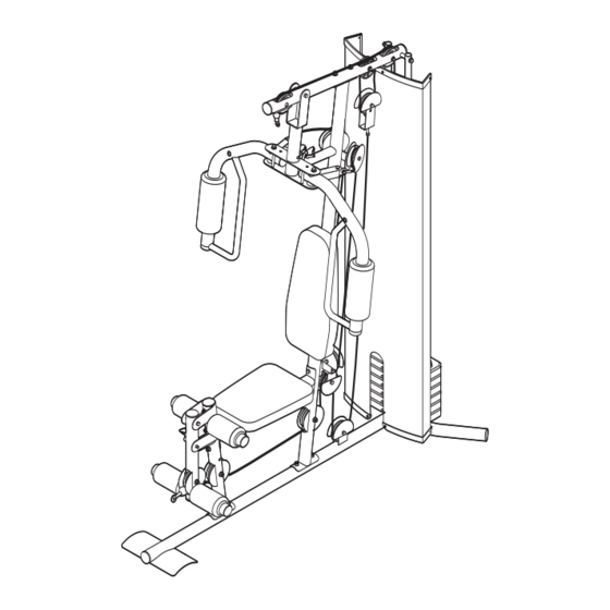
BEFORE YOU BEGIN Thank you for selecting the versatile WEIDER C625 reading this manual, see the front cover of this manu- ® weight system. The weight system offers a selection of al. To help us assist you, please note the product weight stations designed to develop every major mus- model number and serial number before contacting us. -
Page 5: Part Identification Chart
PART IDENTIFICATION CHART See the drawings below to identify small parts used in assembly. The number in parentheses by each drawing is the key number of the part, from the PART LIST near the end of this manual. Note: Some small parts may have been preattached. -
Page 6: Part Identification Chart
ASSEMBLY the packing materials until assembly is complet- Make Assembly Easier Everything in this manual is designed to ensure • Tighten all parts as you assemble them, unless that the weight system can be assembled suc- instructed to do otherwise. cessfully by almost anyone. - Page 7 Frame Assembly Before beginning assembly, make sure that you understand the information in the box on page 6. See the PART IDENTIFICATION CHART on page 5 for help identifying small parts. Insert four M8 x 63mm Carriage Bolts (78) up through the Base (1).
- Page 8 3. Attach the Front Leg (7) to the Base (1) with the two indicated M8 x 63mm Carriage Bolts (78) and two M8 Nylon Locknuts (58). Do not tighten the Nylon Locknuts yet. Attach the Leg Bumper (60) to the Front Leg (7) with an M4 x 20mm Self-tapping Screw (69) and an M4 Washer (33).
-
Page 9: M10 Nylon
6. Attach the Top Frame (4) to the Upright (3) with two M8 x 65mm Bolts (68), two M8 Washers (59), and two M8 Nylon Locknuts (58). Do not tighten the Nylon Locknuts yet. Attach the Top Frame (4) between the Weight Guides (21) with an M10 x 155mm Bolt (74), two M10 Washers (57), two 19mm Spacers (76), and an M10 Nylon Locknut (56). - Page 10 8. Attach the Shroud (17) to the Top Frame (4) with two M6 x 16mm Screws (62) and two M6 Washers (82). Attach the Shroud (17) to the brackets on the Stabilizer (2) with two M6 x 16mm Screws (62) and two M6 Washers (82).
-
Page 11: M8 X 22Mm Shoulder
11. Grease an M10 x 51mm Bolt (66). Attach a Cable Pivot (39) to the Right Arm (9) with the Bolt and Grease an M10 Nylon Locknut (56). Do not overtighten the Nylon Locknut; the Cable Pivot must pivot easily. Wet the inside of a Large Foam Pad (42) with soapy water. - Page 12 14. Identify the two “V”-pulleys (46), which are wider than the other Pulleys (not shown). Route the Arm Cable (54) over a “V”-pulley. Attach the “V”- pulley, a Large Cable Trap (50), two Full Finger Guards (41), and an M10 Washer (57) to the 57 46 Upright (3) with an M10 x 63mm Bolt (75) and an M10 Nylon Locknut (56).
- Page 13 18. Identify the Low Cable (53). Route the Cable through the Leg Lever (8) and the Front Leg (7). Attach a 90mm Pulley (48) inside the Leg Lever (8), over the Low Cable (53), with an M10 x 67mm Bolt (71), two M10 Washers (57), two 12mm Spacers (52), and an M10 Nylon Locknut (56).
- Page 14 22. Route the Low Cable (53) under a 90mm Pulley (48). Attach the Pulley and two Half Finger Guards (43) to the Base (1) with an M10 x 46mm Bolt (81) and an M10 Nylon Locknut (56). Make sure that the Half Finger Guards are on the outside of the bracket as shown.
- Page 15 26. Wrap the High Cable (55) under a 90mm Pulley (48). Attach the Pulley, a Cable Trap (51), and two Half Finger Guards (43) at the upper hole in the “U”-bracket (45) with an M10 x 51mm Bolt (66) and an M10 Nylon Locknut (56). Make sure the Cable Trap is oriented to hold the Cable in the groove of the Pulley and that the Half Finger Guards are on the outside of the “U”-...
-
Page 16: M4 X 20Mm Self-Tapping
Seat Assembly 30. Attach the Backrest (16) to the Upright (3) with two M6 x 63mm Screws (70) and two M6 Washers (82). 31. Attach the Seat (15) to the Seat Frame (6) with two M6 x 63mm Screws (70) and two M6 Washers (82). - Page 17 34. Orient the Curl Pad (14) so that the holes on the back are closer to the lower edge. Attach the Curl Pad to the Curl Post (13) with two M6 x 16mm Screws (62). 35. Make sure that all parts have been properly tightened. The use of the remaining parts will be explained in ADJUSTMENT, beginning on page 18.
-
Page 18: Adjustment
ADJUSTMENT This section explains how to adjust the weight system. See EXERCISE GUIDELINES on page 23 for important information about how to get the most benefit from your exercise program. Also, refer to the accompanying exer- cise guide to see the correct form for several exercises. CHANGING THE WEIGHT SETTING To change the setting of a weight stack, insert a Weight Pin (26) under the desired Weight (22). - Page 19 ARM CONVERSION To use the Arms (9, 10) as butterfly arms, insert the Arm Pins (40) into the holes in the Upright (3) and the Pivot Frame (5) as shown. To use the Arms (9, 10) as press arms, insert the Arm Pins (40) into the holes in the Pivot Frame (5) and the Arms.
-
Page 20: Weight Resistance Chart
WEIGHT RESISTANCE CHART The chart below shows the approximate weight resistance at each exercise station. “Top” refers to the 6-lb. top weight. The other numbers refer to the 12.5-lb. weight plates. Weight resistance shown for the butterfly arm sta- tion is for each arm. Note: The actual resistance at each station may vary due to differences in individual weight plates as well as friction between the cables, pulleys, and weight guides. -
Page 21: Cable Diagram
CABLE DIAGRAM The cable diagram below shows the proper routing of the cables. Use the diagram to make sure that the cables, cable traps, and finger guards have been assembled correctly. If the cables, cable traps, and finger guards have not been assembled correctly, the weight system will not function properly and damage may occur. -
Page 22: Maintenance
MAINTENANCE Make sure that all parts are properly tightened each time the weight system is used. Replace any worn parts immediately. The weight system can be cleaned with a damp cloth and a mild, non-abrasive detergent; do not use solvents to clean the weight system. TIGHTENING THE CABLES Woven cable, the type of cable used on the weight system, can stretch slightly when it is first used. -
Page 23: Exercise Guidelines
EXERCISE GUIDELINES THE FOUR BASIC TYPES OF WORKOUTS The combination of strength training and aerobic exer- cise will reshape and strengthen your body, plus devel- Muscle Building op your heart and lungs. To increase the size and strength of your muscles, PERSONALIZING YOUR EXERCISE PROGRAM push them close to their maximum capacity. - Page 24 The repetitions in each set should be performed COOLING DOWN smoothly and without pausing. The exertion stage of each repetition should last about half as long as the End each workout with 5 to 10 minutes of stretching. return stage. Proper breathing is important. Exhale Include stretches for both your arms and legs.
-
Page 25: Part List
PART LIST—Model No. WEANSY1977.0 R0607A Key No. Qty. Description Key No. Qty. Description Base 11mm Spacer Stabilizer Large Cable Trap Upright Cable Trap Top Frame 12mm Spacer Pivot Frame Low Cable Seat Frame Arm Cable Front Leg High Cable Leg Lever M10 Nylon Locknut Right Arm M10 Washer... -
Page 26: Exploded Drawing
EXPLODED DRAWING—Model No. WEANSY1977.0 R0607A 44 56 56 57... - Page 27 EXPLODED DRAWING—Model No. WEANSY1977.0 R0607A 41 57 41 75...
-
Page 28: Ordering Replacement Parts
ORDERING REPLACEMENT PARTS To order replacement parts, please see the front cover of this manual. To help us assist you, be prepared to pro- vide the following information when contacting the establishment where you purchased this product: • the model number and serial number of the product (see the front cover of the manual) •...
Need help?
Do you have a question about the C 625 and is the answer not in the manual?
Questions and answers