Table of Contents
Advertisement
Model No. WESY3906.1
Serial No.
Write the serial number in the
space above for future reference.
Serial Number Decal (Under Seat)
QUESTIONS?
As a manufacturer, we are com-
mitted to providing complete
customer satisfaction. If you
have questions, or if a part is
damaged or missing, PLEASE
CONTACT OUR CUSTOMER
SERVICE DEPARTMENT
DIRECTLY.
CALL TOLL-FREE:
1-877-992-5999
Mon.–Fri., 6 a.m.–6 p.m. MST
ON THE WEB:
www.weiderservice.com
CAUTION
Read all precautions and instruc-
tions in this manual before using
this equipment. Save this manual
for future reference.
USER'S MANUAL
Visit our website at
www.weiderfitness.com
new products, prizes,
fitness tips, and much more!
Advertisement
Table of Contents

Related Manuals for Weider Club 4870


Summary of Contents for Weider Club 4870
- Page 1 Model No. WESY3906.1 USER’S MANUAL Serial No. Write the serial number in the space above for future reference. Serial Number Decal (Under Seat) QUESTIONS? As a manufacturer, we are com- mitted to providing complete customer satisfaction. If you have questions, or if a part is damaged or missing, PLEASE CONTACT OUR CUSTOMER SERVICE DEPARTMENT...
-
Page 2: Table Of Contents
If a decal is missing or illegible, call the toll-free telephone number on the front cover of this manual and order a free replacement decal. Apply the decal in the location shown. WEIDER is a registered trademark of ICON IP, Inc. -
Page 3: Important Precautions
IMPORTANT PRECAUTIONS WARNING: To reduce the risk of serious injury, read the following important precautions before using the weight system. 1. Read all instructions in this manual and all exercising, stop immediately and make sure warnings on the weight system before using that the cables are on the pulleys. -
Page 4: Before You Begin
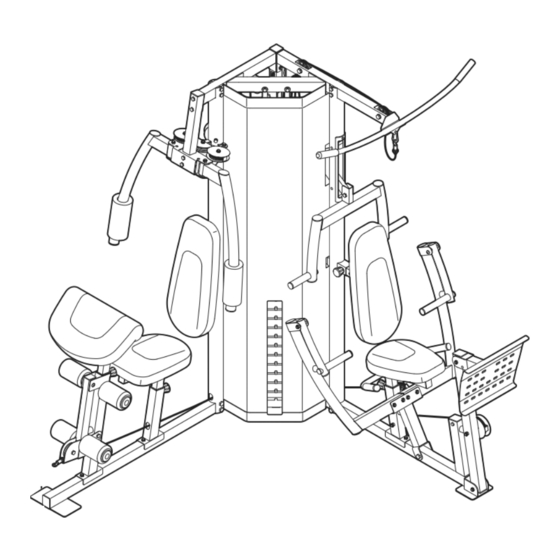
BEFORE YOU BEGIN Thank you for selecting the versatile WEIDER Club model number and serial number before contacting us. ® 4870 weight system. The weight system offers a selec- The model number is WESY3906.1. The serial number tion of weight stations designed to develop every major can be found on a decal attached to the weight system muscle group of the body. -
Page 5: Part Identification Chart
PART IDENTIFICATION CHART Refer to the drawings below and on page 6 to identify small parts used in assembly. The number in parentheses by each drawing is the key number of the part, from the PART LIST on page 32. Note: Some small parts may have been preattached. - Page 6 M10 x 65mm Bolt (87) M10 x 70mm Bolt (57) "V"-pulley (44) Pulley (43) (Not shown to scale) (Not shown to scale) M10 x 75mm Bolt (96) M10 x 80mm Carriage Bolt (88) M6 x 80mm Screw (98) M10 x 90mm Bolt (102) M10 x 95mm Bolt (107) M10 x 100mm Bolt (85) M10 x 120mm Bolt (97)
-
Page 7: Part Identification Chart
ASSEMBLY area and remove the packing materials. Do not dis- Make Assembly Easier pose of the packing materials until assembly is com- pleted. Everything in this manual is designed to ensure that the weight system can be assem- The included hex keys and grease, bled successfully by almost anyone. -
Page 8: M10 Nylon
Frame Assembly Before beginning assembly, make sure you understand the information in the box on the previous page. For help identifying small parts, use the PART IDENTIFICATION CHART on pages 5 and 6. Insert four M10 x 80mm Carriage Bolts (88) up through the Right Base (1). - Page 9 4. Attach the Right Upright (7) to the Right Base (1) with two M10 x 90mm Bolts (102) and two M10 Nylon Locknuts (84). Do not tighten the Nylon Locknuts yet. 5. Attach the Right Seat Upright (11) to the Right Base (1) with the indicated M10 x 80mm Carriage Bolts (88) and two M10 Nylon Locknuts (84).
- Page 10 7. Attach the Left Upright (8) to the Left Base (2) with two M10 x 90mm Bolts (102) and two M10 Nylon Locknuts (84). Do not tighten the Nylon Locknuts yet. 8. Attach the Left Seat Upright (14) to the Left Base (2) with the indicated M10 x 80mm Carriage Bolts (88) and two M10 Nylon Locknuts (84).
- Page 11 10. Attach the Left Top Frame (4) to the Center Upright (9) with two M10 x 70mm Bolts (57), two M10 Washers (108), and an M10 Nylon Locknut (84). Do not tighten the Bolts yet. Attach the Left Top Frame (4) to the Left Upright (8) with two M10 x 90mm Bolts (102) and two M10 Nylon Locknuts (84).
-
Page 12: Arm Assembly
13. Slide eleven 12.5-lb. Weights (34), with the pin grooves on the bottom, onto the Weight Guides (30). Orient a Weight Tube (75) as shown. Insert the Weight Tube into the stack of 12.5-lb. Weights (34). Slide another 12.5-lb. Weight (34) onto the Weight Guides (30). -
Page 13: Bolt
16. Apply grease to a 3" Bushing (71) and the two Large Round Bushings (61) in the Right Butterfly Arm (23). Next, insert the 3" Bushing into the Grease Large Round Bushings. Attach the Butterfly Arm to the Butterfly Frame (24) with an M10 x 100mm Bolt (85) and an M10 Nylon Locknut (84). - Page 14 19. Apply grease to a 2 3/4" Bushing (65) and insert the Bushing into the Left Base (2). Attach the Press Frame to the Left Base (2) with an M10 x 90mm Bolt (102) and an M10 Nylon Locknut (84). Grease 20.
-
Page 15: M8 X 25Mm Shoulder
23. Apply grease to an M10 x 75mm Bolt (96). Attach the Leg Press Plate (29) to the Leg Press (12) Grease with the Bolt and an M10 Nylon Locknut (84). Do not overtighten the Nylon Locknut; the Leg Press Plate must be able to pivot easily. Cable Assembly 24. - Page 16 27. Wrap the Butterfly Cable (73) around a Pulley (43). Attach the Pulley, a Cable Trap (48), an M10 Washer (108), and two Guards (45) to the Right Butterfly Arm (23) with an M10 x 50mm Bolt (105) and an M10 Nylon Locknut (84). Make sure that the Cable Trap is oriented to hold the Cable in the groove of the Pulley.
- Page 17 31. Wrap the Butterfly Cable (73) over a Pulley (43). Attach the Pulley to the Right Top Frame (3) with an M10 x 45mm Bolt (95) and an M10 Nylon Locknut (84). 32. Wrap the Butterfly Cable (73) over a Pulley (43). Attach the Pulley to the Center Top Frame (6) with an M10 x 45mm Bolt (95) and an M10 Nylon Locknut (84).
- Page 18 35. Attach a Pulley (43) inside the Curl Post Upright (10), above the Low Cable (70), with an M10 x 65mm Bolt (87), two M10 Washers (108), two 1/2” Bushings (68), and an M10 Nylon Locknut (84). 36. Route the Low Cable (70) through the Right Seat Upright (11) and the Right Upright (7) and under a Pulley (43).
- Page 19 38. Wrap the Low Cable (70) under a Pulley (43). Attach the Pulley, an M10 Washer (108), and two Half Guards (46) to the Right Base (1) with an M10 x 45mm Bolt (95) and an M10 Nylon Locknut (84). Make sure the Half Guards are oriented as shown.
- Page 20 42. Wrap the Low Cable (70) under a Pulley (43). Attach the Pulley to the Military Press Frame (20) with an M10 x 40mm Bolt (104) and an M10 Nylon Locknut (84). 43. Route the Low Cable (70) up through the Left Top Frame (4) and over a Pulley (43).
- Page 21 47. Wrap the Press Cable (72) under a Pulley (43). Attach the Pulley, a Cable Trap (48), an M10 Washer (108), and two Half Guards (46) to the Left Seat Upright (14) with an M10 x 120mm Bolt (97) and an M10 Nylon Locknut (84). Make sure that the Cable Trap is oriented to hold the Cable in the groove of the Pulley.
- Page 22 Seat Assembly 51. Attach a Backrest (35) to the Right Upright (7) with four M6 x 16mm Screws (99). 52. Attach the Large Seat (37) to the Right Seat Frame (17) with two M6 x 16mm Screws (99), an M6 x 80mm Screw (98), and an M6 Washer (90). Attach the Small Seat (not shown) to the Left Seat Frame (not shown) in the same manner.
- Page 23 55. Attach the Shroud (32) to the Right Upright (7) with six M4 x 16mm Self-tapping Screws (100). Attach the Shroud (32) to the Left Upright (8) in the same manner. 56. Attach the Leg Lever Lock (47) to the Curl Post Upright (10) with an M10 x 70mm Bolt (57), an M10 Washer (108), and an M10 Nylon Locknut (84).
- Page 24 58. Attach the Curl Pad (38) to the Curl Post (16) with two M6 x 16mm Screws (99). 59. Make sure that all parts have been properly tightened. The use of the remaining parts will be explained in ADJUSTMENTS, beginning on page 25. Before using the weight system, pull each cable a few times to make sure that the cables move smoothly over the pulleys.
-
Page 25: Adjustments
ADJUSTMENTS This section explains how to adjust the weight system. See the EXERCISE GUIDELINES on page 29 for important information about how to get the most benefit from your exercise program. Also, refer to the accompanying exer- cise guide to see the correct form for each exercise. Make sure all parts are properly tightened each time the weight system is used. - Page 26 ADJUSTING THE BACKREST To adjust the position of the left Backrest (35), first loosen the indicated Adjustment Knob (69) and disen- gage it from the Backrest Frame (19). Next, move the Backrest to the desired position. Reengage the Knob into the Backrest Frame and retighten the Knob into the Left Upright (8).
-
Page 27: M6 Nylon
USING THE LEG LEVER LOCK When using the low pulley station, engage the Leg Lever Lock (47) onto the Leg Lever (15) tube. TIGHTENING THE CABLES Woven cable, the type of cable used on the weight system, can stretch slightly when it is first used. If there is slack in the cables before resistance is felt, the cables should be tightened. -
Page 28: Cable Diagram
CABLE DIAGRAM The cable diagrams below show the proper routing of the Low Cable (70), the Press Cable (72), and the Butterfly Cable (73). Use the diagrams to make sure that the cables, the cable traps, and the guards have been assembled correctly. -
Page 29: Exercise Guidelines
EXERCISE GUIDELINES THE FOUR BASIC TYPES OF WORKOUTS PERSONALIZING YOUR EXERCISE PROGRAM Muscle Building Determining the exact length of time for each workout, To increase the size and strength of your muscles, as well as the number of repetitions or sets completed, push them close to their maximum capacity. -
Page 30: Muscle Chart
Rest for a short period of time after each set. The slowly as you stretch and do not bounce. Ease into ideal resting periods are: each stretch gradually and go only as far as you can • Rest for three minutes after each set for a muscle without strain. - Page 31 NOTES...
-
Page 32: Part List
PART LIST—Model No. WESY3906.1 R0606C Qty. Description Qty. Description Qty. Description Right Base Upright Bushing Lock Left Base Upright Cover Lock Pin Right Top Frame Handgrip 2" x 2 1/2" Inner Cap Left Top Frame Pulley Ankle Strap Center Base “V”-pulley Weight Clip Center Top Frame... -
Page 33: Exploded Drawing
EXPLODED DRAWING—Model No. WESY3906.1 R0606C 42 59 62 100... - Page 34 EXPLODED DRAWING—Model No. WESY3906.1 R0606C...
- Page 35 EXPLODED DRAWING—WESY3906.1 R0606C 43 68 43 48...
-
Page 36: Ordering Replacement Parts
• the MODEL NUMBER of the product (WESY3906.1) • the NAME of the product (WEIDER CLUB 4870 weight system) • the SERIAL NUMBER of the product (see the front cover of this manual) • the KEY NUMBER and DESCRIPTION of the part(s) (see the PART LIST and EXPLODED DRAWING on...
Need help?
Do you have a question about the Club 4870 and is the answer not in the manual?
Questions and answers