Table of Contents
Advertisement
Model No. WEBE8077.0
Serial No.
Write the serial number in the
space above for future reference.
Serial Number Decal (under seat)
QUESTIONS?
As a manufacturer, we are com-
mitted to providing complete
customer satisfaction. If you
have questions, or if parts are
missing or damaged, PLEASE
DO NOT CONTACT THE STORE.
For assistance, contact our
Customer Service Department.
CALL TOLL-FREE:
1-877-992-5999
Mon.–Fri. 6 a.m.–6 p.m. MST
Sat. 8 a.m.–4 p.m. MST
ON THE WEB:
www.weiderservice.com
CAUTION
Read all precautions and instruc-
tions in this manual before using
this equipment. Save this manual
for future reference.
USER'S MANUAL
Visit our website at
www.proform.com
new products, prizes,
fitness tips, and much more!
Visit our website at
www.healthrider.com
new products, prizes,
fitness tips, and much more!
Visit our website at
www.nordictrack.com
new products, prizes,
fitness tips, and much more!
Visit our website at
www.weiderfitness.com
new products, prizes,
fitness tips, and much more!
Advertisement
Table of Contents

Related Manuals for Weider C 875


Summary of Contents for Weider C 875
- Page 1 Model No. WEBE8077.0 USER’S MANUAL Serial No. Write the serial number in the space above for future reference. Visit our website at www.proform.com Serial Number Decal (under seat) new products, prizes, fitness tips, and much more! QUESTIONS? As a manufacturer, we are com- mitted to providing complete customer satisfaction.
-
Page 2: Table Of Contents
Apply the decal in the location shown. Note: The decals may not be shown at actual size. WEIDER is a registered trademark of ICON IP, Inc. -
Page 3: Important Precautions
IMPORTANT PRECAUTIONS WARNING: To reduce the risk of serious injury, read all important precautions and instructions in this manual and all warnings on the weight bench before using the weight bench. ICON assumes no responsibility for personal injury or property damage sustained by or through the use of the weight bench. -
Page 4: Before You Begin
BEFORE YOU BEGIN Thank you for selecting the versatile WEIDER ® C875 manual. To help us assist you, note the product model weight bench. The weight bench offers an impressive number and serial number before contacting us. The selection of exercise stations designed to develop model number and the location of the serial number every major muscle group of the body. -
Page 5: Part Identification Chart
PART IDENTIFICATION CHART See the drawings below to identify small parts used in assembly. The number in parentheses by each drawing is the key number of the part, from the PART LIST near the end of this manual. Note: Some small parts may have been preattached. - Page 6 M4 x 16mm Self-tapping Screw (147) 13mm x 15mm Spacer (154) Curl Bar Spacer (178) M4 x 20mm Self-tapping Screw (120) 13mm x 63mm Spacer (54) M4 x 30mm Self-tapping Screw (79) Backrest Support Spacer (51) M6 x 15mm Bolt (144) M6 x 16mm Screw (141) M10 x 6.5mm M10 x 25mm...
-
Page 7: Assembly
ASSEMBLY packing materials. Do not dispose of the packing Make Assembly Easier materials until assembly is completed. Everything in this manual is designed to ensure • Tighten all parts as you assemble them, unless that the weight bench can be assembled suc- instructed to do otherwise. -
Page 8: Backrest Support
3. Attach the Front Leg (3) to the Bench Frame (1) with two M10 x 100mm Screws (117) and two M10 Washers (148). Tighten the Screws used in steps 1 and 3. 4. Attach the Backrest (32) to the Backrest Frame (8) with four M6 x 20mm Screws (122). - Page 9 6. Grease an M10 x 165mm Bolt (123). Attach the Backrest Supports (7) and two Backrest Bushings (48) to the Bench Frame (1) with the Bolt, two M10 Washers (148), and an M10 Nylon Locknut (153). Do not overtighten the Nylon Locknut; the Backrest Supports must pivot easily.
- Page 10 9. Slide the Weight Spacer (160) onto the Leg Lever (4). Grease the outside of the barrel of an M10 x 83mm Bolt Set (118). Attach the Leg Lever (4) to the Front Leg (3) with the Bolt Set. Make sure that the barrel of the Bolt Set is inserted through both sides of the bracket on the Leg Lever.
-
Page 11: Large
12. Attach the Curl Pad (34) to the Curl Post (10) with two M6 x 20mm Screws (122). 13. Orient one of the Front Uprights (11) and one of the Base Feet (16) as shown. Attach the Front Upright and the Base Foot to the Base (14) with two M10 x 155mm Screws (131). - Page 12 14. Orient a Rear Upright (12) as shown. Attach the Rear Upright to the Base (14) with two M10 x 110mm Screws (130) and two M10 Washers (148). Do not tighten the Screws yet. Attach the other Rear Upright (12) to the Base (14) in the same way.
- Page 13 16. Orient the Center Upright (13) as shown and insert it into the Base (14). Hold the Foot Plate (15) and the Weight Carriage Base (20) against the Base. Attach the Foot Plate, Center Upright, Bracket and Weight Carriage Base to the Base with two M10 x 110mm Screws (130).
- Page 14 18. Attach the Left Spotter Hook (115) to a Barbell Spotter (109) with an M10 x 25mm Bolt (166) and an M10 Nylon Locknut (153). Do not overtighten the Nylon Locknut; the Left Spotter Hook Long End must pivot easily. Identify a Barbell Guide (112), which is slightly shorter than a Weight Carriage Guide (not shown).
- Page 15 20. Attach a Barbell Guide (112) to the Top Frame (17) with an M10 x 55mm Bolt (127), two M10 Washers (148), two M10 x 6.5mm Spacers (151), and an M10 Nylon Locknut (153). Attach the other Barbell Guide (not shown) to the Top Frame (17) in the same way.
-
Page 16: M10 Large
23. Attach the Weight Carriage Frame (18) to the Weight Carriage Guides (21) with two M8 x 40mm Bolts (136) and two M8 Nylon Locknuts (170). Do not tighten the Nylon Locknuts yet. 24. Attach the Weight Carriage Frame (18) to the Center Upright (13) and the Top Frame (17) with two M10 x 25mm Screws (128). - Page 17 26. Grease the bottom of the Right Adjustment Bracket (24), and slide the Right Arm (23) onto the Right Adjustment Bracket. See the inset drawing. Orient two Bracket Retainers (73) so that the teeth bend downward, and press them onto the Right Adjustment Bracket. Attach the Right Arm (23) to Right Adjustment Grease Bracket (24) with an M10 x 30mm Screw (134),...
- Page 18 29. Orient the Locking Bar (114) as shown. Hold the Locking Bar between the left Barbell Carriage (104) and the right Barbell Carriage (not shown). Insert the Barbell (113) into the left Barbell Carriage, the Locking Bar, and the right Barbell Carriage.
- Page 19 32. Tighten three Weight Storage Tubes (67) onto a Rear Upright (12). Attach the remaining three Weight Storage Tubes (not shown) onto the other Rear Upright (12) in the same way. 33. Attach an Upright Pin/Tether (28) to a Weight Rest (26) with an M4 x 16mm Self-tapping Screw (147).
- Page 20 34. See the CABLE DIAGRAM on page 34 to iden- tify the cables as you assemble them. Grease Identify the Arm Cable (145). Grease an M8 x 22mm Shoulder Bolt (143). Attach the Cable to the Left Adjustment Bracket (25) with the Shoulder Bolt and an M8 Nylon Locknut (170).
- Page 21 37. Wrap the Arm Cable (145) over a “V”-pulley (75). Attach the “V”-pulley, a Large Cable Trap (77), and two Full Pulley Guards (76) to the other side of the bracket on the Center Upright (13) with an M10 x 60mm Bolt (133) and an M10 Nylon Locknut (153).
- Page 22 40. Wrap the High Cable (81) around a Small Pulley (74). Attach the Small Pulley to the Top Frame (17) with an M10 x 45mm Bolt (140) and an M10 Nylon Locknut (153). 153 74 41. Feed the High Cable (81) through the indicated slot in the Top Frame (17).
- Page 23 43. Wrap the High Cable (81) under a Small Pulley (74). Attach the Cable, a Small Cable Trap (93), and two Half Pulley Guards (91) to the second hole from the top of the “U”-bracket (158) with an M10 x 48mm Bolt (125) and an M10 Nylon Locknut (153).
- Page 24 45. Feed the High Cable (81) through the indicated slot in the Top Frame (17). Wrap the Cable around a Small Pulley (74). Attach the Small Slot Pulley to the Top Frame with an M10 x 45mm Bolt (140) and an M10 Nylon Locknut (153). 46.
- Page 25 47. Wrap the High Cable (81) over a Large Pulley (165). Attach the Large Pulley to the Swivel Bracket (31) with an M10 x 55mm Bolt (127), two M10 Washers (148), two M10 x 6.5mm Spacers (151), and an M10 Nylon Locknut (153). Tighten the Cable Eyelet (174) as far as possible onto the end of the High Cable (81).
- Page 26 50. Wrap the Rear Cable (94) under a Small Pulley (74). Attach the Small Pulley, a Small Cable Trap (93), and two Half Pulley Guards (91) at the sec- ond hole from either end of the two Pulley Plates (92) with an M10 x 48mm Bolt (125) and an M10 Nylon Locknut (153).
- Page 27 53. Wrap the Low Cable (80) over a Small Pulley (74). Attach the Small Pulley and two Half Pulley Guards (91) to the Double “U”-bracket (98) with an M10 x 45mm Bolt (140) and an M10 Nylon Locknut (153). Make sure that the Half Pulley Guards are oriented as shown.
- Page 28 56. Wrap the Low Cable (80) under a Small Pulley (74). Attach the Small Pulley and two Half Pulley Guards (91) to the Weight Carriage Base (20) with an M10 x 45mm Bolt (140) and an M10 Nylon Locknut (153). Make sure that the Half Pulley Guards are oriented as shown.
-
Page 29: Adjustment
ADJUSTMENT This section explains how to adjust the weight bench. See the EXERCISE GUIDELINES on page 35 for impor- tant information about how to get the most benefit from your exercise program. Also, refer to the accompanying exercise guide to see the correct form for several exercises. ADJUSTING THE SEAT AND BACKREST To adjust the position of the Seat (33) and the Backrest (32), first pull the Seat Knob (56). - Page 30 USING THE LEG LEVER To use the Leg Lever (4), slide the desired weights (not included) onto the Leg Lever. Secure the weights with the Weight Clip (132). You can store unused weights on the weight storage tubes (not shown) on the rear uprights.
- Page 31 USING THE LOCKING BAR Grip the Locking Bar (114) with both hands. Turn the Locking Bar until the two hooks disengage the slots in Hook the Front Uprights (11). Raise or lower the Locking Bar to a new position and turn it until the hooks engage slots in the Front Uprights.
- Page 32 ATTACHING THE ACCESSORIES TO THE HIGH PULLEY STATION To use the high pulley station, first place the desired weights on the weight carriage (see ADDING WEIGHTS TO THE BARBELL OR THE WEIGHT CARRIAGE on page 31). Next, attach the Lat Bar (58) to the High Cable (81) with a Cable Clip (63).
-
Page 33: Maintenance
MAINTENANCE Make sure that all parts are properly tightened each time the weight bench is used. Replace any worn parts immediately. The weight bench can be cleaned with a damp cloth and a mild, non-abrasive detergent; do not use solvents to clean the weight bench. TIGHTENING THE CABLES Woven cable, the type of cable used on the weight bench, can stretch slightly when it is first used. -
Page 34: Cable Diagram
CABLE DIAGRAM The diagram below shows the proper routing of the cables. The numbers in each drawing show the proper rout- ing for that cable. Use the diagram to make sure that the cables, cable traps, and pulley guards are assembled correctly. -
Page 35: Exercise Guidelines
EXERCISE GUIDELINES THE FOUR BASIC TYPES OF WORKOUTS PERSONALIZING YOUR EXERCISE PROGRAM Muscle Building Determining the appropriate length of time for each To increase the size and strength of your muscles, workout, and the numbers of repetitions and sets to push them close to their maximum capacity. - Page 36 COOLING DOWN The repetitions in each set should be performed smoothly and without pausing. The exertion stage of each repetition should last about half as long as the End each workout with 5 to 10 minutes of stretching. return stage. Proper breathing is important. Exhale Include stretches for both your arms and legs.
- Page 37 EXERCISE WEIGHT SETS REPS MONDAY Date: TUESDAY AEROBIC EXERCISE Date: EXERCISE WEIGHT SETS REPS WEDNESDAY Date: THURSDAY AEROBIC EXERCISE Date: EXERCISE WEIGHT SETS REPS FRIDAY Date: Make photocopies of this page for scheduling and recording your workouts.
-
Page 38: Part List
PART LIST—Model No. WEBE8077.0 R0607A Key No. Qty. Description Key No. Qty. Description Bench Frame Backrest Support Spacer Rear Leg Roller Spacer Front Leg Seat Carriage Roller Leg Lever 13mm x 63mm Spacer Curl Bar Frame Seat Carriage Bushing Seat Carriage Seat Knob Backrest Support Pulley Handle... -
Page 39: M8 X 22Mm Shoulder
PART LIST—Model No. WEBE8077.0 R0607A Key No. Qty. Description Key No. Qty. Description 38mm x 100mm Inner Cap M8 x 22mm Shoulder Bolt Barbell Adapter M6 x 15mm Bolt 48mm x 3mm Round Inner Cap Arm Cable Barbell Carriage M8 x 65mm Bolt Bar Slide Bushing M4 x 16mm Self-tapping Screw Barbell Bushing... -
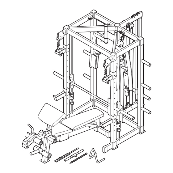
Page 40: Exploded Drawing
EXPLODED DRAWING A—Model No. WEBE8077.0 R0607A... - Page 41 EXPLODED DRAWING B—Model No. WEBE8077.0 R0607A...
- Page 42 EXPLODED DRAWING C—Model No. WEBE8077.0 R0607A...
- Page 43 EXPLODED DRAWING D—Model No. WEBE8077.0 R0607A...
-
Page 44: Ordering Replacement Parts
ORDERING REPLACEMENT PARTS To order replacement parts, please see the front cover of this manual. To help us assist you, be prepared to pro- vide the following information when contacting us: • the model number and serial number of the product (see the front cover of the manual) •...
Need help?
Do you have a question about the C 875 and is the answer not in the manual?
Questions and answers