
Related Manuals for Regency Ceiling Fans Regulator


Summary of Contents for Regency Ceiling Fans Regulator
- Page 1 Style that revolves around you. • C • EILING WNER'S ANUAL EAD AND HESE NSTRUCTIONS • R • EGULATOR 09/08 WARNING: Read and follow these instructions carefully and be mindful of all warnings shown throughout.
- Page 2 & O ENERAL NSTALLATION PERATION NSTRUCTIONS MPORTANT AFEGUARDS: To ensure the success of the installation, be sure to read the instructions and review the diagrams thoroughly To ensure the success of the installation, be sure to read the instructions and review the diagrams thoroughly before beginning.
-
Page 3: Important Safety Precautions
MPORTANT AFETY RECAUTIONS Thank you for choosing a Regency Ceiling Fan. You have chosen the best! Your new ceiling fan has been designed to provide many years of service and enjoyment. Warnings: Warnings: • Disconnect power by removing fuse or turning off circuit breaker before installing the fan and/or optional lighting. Disconnect power by removing fuse or turning off circuit breaker before installing the fan and/or optional lighting. -
Page 4: Unpacking Your Fan
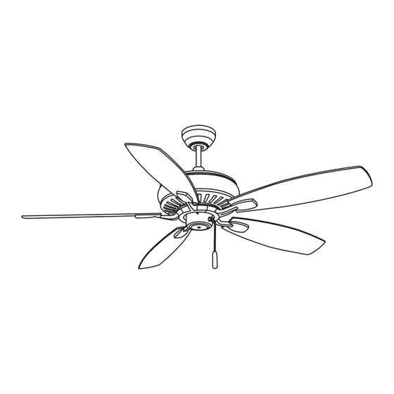
NPACKING 1. Unpack your fan and check the contents. Do not discard the carton. If warranty replacement or repair is ever necessary, the fan should be returned in original packing. Remove all parts and hardware. Do not lay motor housing on its side, or the decorative housing may shift, be bent or damaged. 2. - Page 5 REPARATION Parts identification on assembled fan Canopy Downrod Blade Collar Cover Motor Housing Blade arm Detachable Pull chain Switch Housing with fob PREPARATION: Verify you have all parts before beginning the installation. Check foam insert closely for missing parts. Remove motor from packing.
- Page 6 NSTALLING THE OUNTING RACKET AND ANGING RACKET Caution: Caution: To avoid possible electrical shock, be sure electricity is turned off at the main power box before wiring. All wiring must be in accordance with National and Local Electrical Codes and the ceiling fan must be grounded as a precaution Outlet against possible electric shock.
- Page 7 NSTALLING THE 1. Carefully support fan body (motor) in its styrofoam packing with the mounting collar (where the wires come out) facing upward. 2. Loosen the two set screws and remove the downrod pin and cotter pin from the top coupling of the motor assembly. 3.
-
Page 8: Electrical Connections
NSTALLING THE ONTINUED WARNING: WARNING: To avoid damaging the blade arms and blades, do not install them onto fan until fan is fastened to ceiling. 1. Lift ball/downrod/fan into hanging bracket opening. NOTE: NOTE: The tab opposite hanging bracket opening should fit in slot on ball. -
Page 9: Finishing The Installation
INISHING THE NSTALLATION 1. Tuck connections neatly into ceiling outlet box. Ceiling Fan 2. Slide the canopy up to ceiling and over the 2 screws on Outlet Box the hanger bracket. Rotate canopy clockwise. Next, while Hanger Bracket holding the canopy with one hand, slide the canopy screw cover plate over the screws and rotate clockwise Screws until tight. -
Page 10: Switch Housing
NSTALLATION OF ETACHABLE WITCH OUSING OUNTING 1. Remove one of the three screws on the mounting hub located on the fan motor. 2. Loosen the other two screws. 3. Install detachable switch housing mounting hub to mounting hub. 4. Pass the 2 light wires through the center hole of the detachable switch housing mounting hub. 5. - Page 11 NSTALLING THE EMOVABLE WITCH OUSING NOTE: Be sure the power is off before installing. NOTE: Be sure the power is off before installing. 1. Loosen the 3 side screws on detachable mounting plate halfway. 2. If installing light kit, carefully remove light kit cover in bottom of switch housing. Attach the light kit to the switch housing per instructions supplied with light kit.
-
Page 12: Operation
PERATION Turn on the power and check operation of the fan. The fan is controlled by the use of the pull chain as follows: one pull = high speed two pulls = medium speed three pulls = low speed four pulls = off For proper functions, ensure that the chain is pulled down fully and released each time. -
Page 13: Troubleshooting
ARE AND LEANING Periodically it may be necessary to re-tighten blade to blade arm screws or blade arm to motor screws to prevent clicking or humming sound during operation. This is especially true in climates with broad temperature and humidity ranges. When dusting the blades, you must support the blade to prevent bending - no pressure should be applied to the blades.
Need help?
Do you have a question about the Regulator and is the answer not in the manual?
Questions and answers