Table of Contents
Advertisement
www.nordictrack.com
Model No. 831.23922.0
USER’'S MANUAL
Serial No.
Write the serial number in the space
above for reference.
Serial Number
Decal
ACTIVATE YOUR
WARRANTY
To register your product and
activate your warranty today, go
to www.nordictrackservice.com/
registration.
CUSTOMER CARE
For service at any time, go to
www.nordictrackservice.com.
Or call 1-800-TO-BE-FIT
(1-800-862-3348)
Mon.––Fri. 6 a.m.––6 p.m. MT
Sat. 8 a.m.––4 p.m. MT
Please do not contact the store.
CAUTION
Read all precautions and instruc-
tions in this manual before using
this equipment. Keep this manual
for future reference.
Advertisement
Table of Contents

Related Manuals for NordicTrack E 12.5 Elliptical


Summary of Contents for NordicTrack E 12.5 Elliptical
- Page 1 Model No. 831.23922.0 USER’’S MANUAL Serial No. Write the serial number in the space above for reference. Serial Number Decal ACTIVATE YOUR WARRANTY To register your product and activate your warranty today, go to www.nordictrackservice.com/ registration. CUSTOMER CARE For service at any time, go to www.nordictrackservice.com.
-
Page 2: Table Of Contents
Apply the decal in the location shown. Note: The decal(s) may not be shown at actual size. NORDICTRACK is a registered trademark of ICON IP, Inc. -
Page 3: Important Precautions
IMPORTANT PRECAUTIONS WARNING: To reduce the risk of burns, fire, electric shock, or injury to persons, read all important precautions and instructions in this manual and all warnings on your elliptical before using your elliptical. ICON assumes no responsibility for personal injury or property damage sus- tained by or through the use of this product. - Page 5 STANDARD SERVICE PLANS...
-
Page 6: Before You Begin
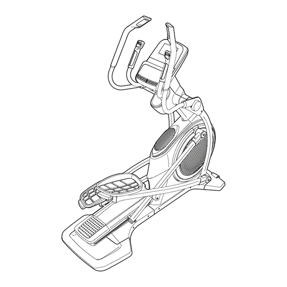
NORDICTRACK ® E 12.5 elliptical. The E 12.5 elliptical manual. To help us assist you, note the product model provides an impressive selection of features designed number and serial number before contacting us. The... -
Page 7: Part Identification Chart
PART IDENTIFICATION CHART Use the drawings below to identify the small parts needed for assembly. The number in parentheses below each drawing is the key number of the part, from the PART LIST near the end of this manual. The number following the key number is the quantity needed for assembly. -
Page 8: Assembly
ASSEMBLY •• To watch an assembly •• Left parts are marked ““L”” or ““Left”” and right parts video, go to are marked ““R”” or ““Right.”” http://productvideo.co/ assembly/sears/nordic- •• To identify small parts, see page 7. track or use your mobile phone or smartphone to ••... - Page 9 2. Remove the screws (not shown) and the ship- ping bracket (not shown) from the front of the Frame (1). Discard the screws. With the help of a second person, place the ship- ping bracket (not shown) under the front of the Frame (1).
- Page 10 4. Remove the screws (not shown) and the ship- ping bracket (not shown) from the rear of the Frame (1). Discard the screws. With the help of a second person, place the ship- ping bracket (not shown) under the rear of the Frame (1).
- Page 11 7. Connect the Fan Wire (114) to the Fan Extension Wire (143). Wire Locate the wire tie in the Upright (4). Tie the lower end of the wire tie to the Main Wire (110). Then, pull the upper end of the wire tie until the Main Wire is routed through the Upright.
- Page 12 9. Identify the Left and Right Inner Covers (55, 68) and orient them as shown. Slide the Left Inner Cover (55) onto the left side of the Upright (4). Then, slide the Right Inner Cover (68) onto the right side of the Upright. 10.
- Page 13 11. Tighten an M8 x 16mm Screw (120) and an M8 x 25mm Washer (98) into each end of the Pivot Axle (35) at the same time. 12. Identify the Right Pedal (49) and the Right Pedal Arm (58), and orient them as shown. Attach the Right Pedal (49) to the Right Pedal Bracket (139) on the Right Pedal Arm (58) with five M6 x 12mm Screws (121).
- Page 14 13. Orient the Left Pedal Arm (44) as shown. Apply grease to the axle on the Left Pedal Arm (44). Attach the Left Pedal Arm (44) to the Left Roller Arm (12) with an M8 x 16mm Screw (120), a Roller Arm Cover (81), and an M8 x 25mm Grease Washer (98).
- Page 15 15. Slide the Right Upper Body Leg (36) onto the Right Upper Body Arm (61). Attach the Right Upper Body Leg (36) with two M8 x 35mm Bolts (96) and two M8 Locknuts (102). Make sure that the Locknuts are in the hexagonal holes.
- Page 16 17. Untie and discard the wire tie on the Main Wire (110). While a second person holds the Console (7) near the Upright (4), connect the wires on the Console to the Main Wire (110), to the Right and Left Sensor Wires (63, 69), and to the Fan Extension Wire (143).
- Page 17 20. Press the Front Upright Cover (91) onto the Rear Upright Cover (80). Attach the Front Upright Cover (91) to the Upright (4) with a #8 x 3/4" Screw (123). 21. Make sure that all parts are properly tightened before you use the elliptical. Note: Extra parts may be included.
-
Page 18: The Chest Heart Rate Monitor
THE CHEST HEART RATE MONITOR HOW TO PUT ON THE HEART RATE MONITOR •• Do not expose the heart rate monitor to direct sun- light for extended periods of time; do not expose it to The heart rate temperatures above 122° F (50° C) or below 14° F monitor consists of (-10°... -
Page 19: How To Use The Elliptical
HOW TO USE THE ELLIPTICAL HOW TO PLUG IN THE POWER CORD A temporary adapter may 2-pole Receptacle This product must be grounded. If it should malfunc- be used to tion or break down, grounding provides a path of least connect the Adapter resistance for electric current to reduce the risk of... - Page 20 HOW TO MOVE THE ELLIPTICAL HOW TO EXERCISE ON THE ELLIPTICAL Due to the size and weight of the elliptical, moving To mount the elliptical, hold the upper body arms or it requires two persons. Stand in front of the elliptical, the handlebars and step onto the pedal that is in the hold the upright, and place one foot against one of the lower position.
- Page 21 CONSOLE DIAGRAM MAKE YOUR FITNESS GOALS A REALITY WITH IFIT.COM Upload your workout results to the iFit cloud and track your accomplishments. With your new iFit-compatible fitness equipment, you can use an array of features on iFit.com to make your Set calorie, time, or distance goals for your fitness goals a reality: workouts.
- Page 22 FEATURES OF THE CONSOLE HOW TO TURN ON THE POWER The advanced console offers an array of features IMPORTANT: If the elliptical has been exposed to designed to make your workouts more effective and cold temperatures, allow it to warm to room tem- enjoyable.
- Page 23 HOW TO SET UP THE CONSOLE HOW TO USE THE MANUAL MODE Before using the elliptical for the first time, set up the 1. Begin pedaling or press any button on the console. console to turn on the console. 1. Create an iFit account. See HOW TO TURN ON THE POWER on page 22.
- Page 24 4. Follow your progress with the display. Time——When the manual mode is selected, this display mode will show the elapsed time. The display can show the following workout information: The matrix offers several display tabs. Press the Display button repeatedly until the desired tab is shown.
- Page 25 When a wireless iFit When your pulse is detected, one or two dashes module is connected, will appear, and then your heart rate will be shown. the wireless symbol at For the most accurate heart rate reading, hold the top of the display the contacts for at least 15 seconds.
- Page 26 HOW TO USE AN ONBOARD WORKOUT As you exercise, you will be prompted to keep your pedaling speed near the target rpm for the cur- 1. Begin pedaling or press any button on the rent segment. When an upward-pointing arrow console to turn on the console.
- Page 27 HOW TO USE A SET-A-GOAL WORKOUT Note: The calorie goal is an estimate of the number of calories that you will burn during 1. Begin pedaling or press any button on the the workout. The actual number of calories that console to turn on the console.
- Page 28 HOW TO USE AN IFIT WORKOUT of calories you will burn during the workout and a profile of the resistance settings of the workout. Note: To use an iFit workout, the console must be connected to a wireless network (see page 29). An Note: The calorie goal is an estimate of the iFit account is also required (see step 1 on page 23).
- Page 29 HOW TO CHANGE CONSOLE SETTINGS Firmware Update——For the best results, regularly check for firmware updates. The console features a settings mode that allows you to view usage information, to personalize console set- Note: The matrix will display NOT CONNECTED if tings, and to set up and manage a wireless network the console is not connected to a wireless network.
- Page 30 option. Clear WiFi——To erase the console’’s wireless network settings and have it forget the currently Press the up, down, left, and right buttons to high- selected wireless network, follow the instructions in light the desired letter or number. Then, press the the matrix.
- Page 31 Then, cycle the power of the elliptical: press the computer, smart phone, tablet, or other Wi-Fi power switch on the elliptical to the off position, device. Next, type in the IP address on the con- wait for several seconds, and then press the power sole into the URL bar in your browser.
-
Page 32: Fcc Information
FCC INFORMATION This equipment has been tested and found to comply with the limits for a Class B digital device, pursuant to part 15 of the FCC Rules. These limits are designed to provide reasonable protection against harmful interference in a residential installation. This equipment generates, uses, and can radiate radio frequency energy and, if not installed and used in accordance with the instructions, may cause harmful interference to radio communications. -
Page 33: Maintenance And Troubleshooting
MAINTENANCE AND TROUBLESHOOTING Inspect and tighten all parts of the elliptical regularly. HOW TO ADJUST THE DRIVE BELT Replace any worn parts immediately. If the pedals slip while you are pedaling, even while To clean the elliptical, use a damp cloth and a small the resistance is adjusted to the highest level, the drive amount of mild soap. - Page 34 Loosen the M6 x Locate and loosen 12mm Hex Screw (85) the Idler Screw (101). and the M10 x 58mm Next, tighten the Belt Hex Bolt (86). Then, Adjustment Screw (88) remove the right Crank until the Drive Belt Arm (20). Gently move (113) is tight.
- Page 35 HOW TO ADJUST THE REED SWITCH If the console does not display correct feedback, the reed switch should be adjusted. To adjust the reed switch, first remove the three M4 x 16mm Screws (104) and the M4 x 16mm Machine Screw (128) from the left Disc (71).
-
Page 36: Exercise Guidelines
EXERCISE GUIDELINES Burning Fat——To burn fat effectively, you must exer- WARNING: cise at a low intensity level for a sustained period of Before beginning this time. During the first few minutes of exercise, your or any exercise program, consult your physi- body uses carbohydrate calories for energy. - Page 37 SUGGESTED STRETCHES The correct form for several basic stretches is shown at the right. Move slowly as you stretch; never bounce. 1. Toe Touch Stretch Stand with your knees bent slightly and slowly bend forward from your hips. Allow your back and shoulders to relax as you reach down toward your toes as far as possible.
-
Page 38: Part List
PART LIST Model No. 831.23922.0 R0113A Key No. Qty. Description Key No. Qty. Description Frame Roller Rear Stabilizer Cover Fan Grill Ramp Axle Cover Upright Left Outer Cover Rear Stabilizer Left Inner Cover Front Stabilizer Lower Upright Cover Console Roller Arm Bushing Front Stabilizer Cover Right Pedal Arm Bottom Ramp Cover... - Page 39 Key No. Qty. Description Key No. Qty. Description Idler Screw M4 x 16mm Machine Screw M8 Locknut M8 x 23mm Washer Pedal Pin Heart Rate Monitor M4 x 16mm Screw Chest Strap M8 x 16mm Hex Screw 1" Grommet M4 x 13mm Screw Crank Arm Bushing Standoff Ramp Shield...
-
Page 40: Exploded Drawing
EXPLODED DRAWING A Model No. 831.23922.0 R0113A... - Page 41 EXPLODED DRAWING B Model No. 831.23922.0 R0113A...
- Page 42 EXPLODED DRAWING C Model No. 831.23922.0 R0113A...
- Page 43 EXPLODED DRAWING D Model No. 831.23922.0 R0113A...
-
Page 44: Ordering Replacement Parts
ORDERING REPLACEMENT PARTS To order replacement parts, please see the front cover of this manual. To help us assist you, be prepared to provide the following information when contacting us: •• the model number and serial number of the product (see the front cover of this manual) ••...
Need help?
Do you have a question about the E 12.5 Elliptical and is the answer not in the manual?
Questions and answers