Table of Contents
Advertisement
www.nordictrack.com
Model No. NTEL18913.0
USER’'S MANUAL
Serial No.
Write the serial number in the space
above for reference.
Serial Number
Decal
ACTIVATE YOUR
WARRANTY
To register your product and
activate your warranty today, go
to www.nordictrackservice.com/
registration.
CUSTOMER CARE
For service at any time, go to
www.nordictrackservice.com.
Or call 1-800-TO-BE-FIT
(1-800-862-3348)
Mon.––Fri. 6 a.m.––6 p.m. MT
Sat. 8 a.m.––12 p.m. MT
Please do not contact the store.
CAUTION
Read all precautions and instruc-
tions in this manual before using
this equipment. Keep this manual
for future reference.
Advertisement
Table of Contents

Subscribe to Our Youtube Channel
Related Manuals for NordicTrack E 11.7 Elliptical


Summary of Contents for NordicTrack E 11.7 Elliptical
- Page 1 Model No. NTEL18913.0 USER’’S MANUAL Serial No. Write the serial number in the space above for reference. Serial Number Decal ACTIVATE YOUR WARRANTY To register your product and activate your warranty today, go to www.nordictrackservice.com/ registration. CUSTOMER CARE For service at any time, go to www.nordictrackservice.com.
-
Page 2: Table Of Contents
If a decal is missing or illegible, see the front cover of this manual and request a free replacement decal. Apply the decal in the location shown. Note: The decal(s) may not be shown at actual size. NORDICTRACK is a registered trademark of ICON IP, Inc. -
Page 3: Important Precautions
IMPORTANT PRECAUTIONS WARNING: To reduce the risk of burns, fire, electric shock, or injury to persons, read all important precautions and instructions in this manual and all warnings on your elliptical before using your elliptical. ICON assumes no responsibility for personal injury or property damage sus- tained by or through the use of this product. - Page 5 STANDARD SERVICE PLANS...
-
Page 6: Before You Begin
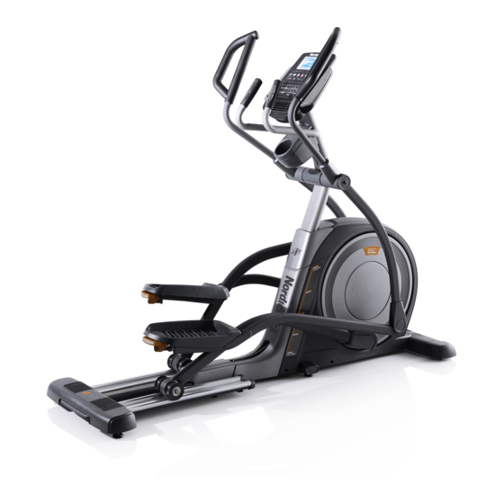
NORDICTRACK ® E 11.7 elliptical. The ELITE E 11.7 manual. To help us assist you, note the product model elliptical provides an impressive selection of features number and serial number before contacting us. The... -
Page 7: Part Identification Chart
PART IDENTIFICATION CHART Use the drawings below to identify the small parts needed for assembly. The number in parentheses below each drawing is the key number of the part, from the PART LIST near the end of this manual. The number following the key number is the quantity needed for assembly. -
Page 8: Assembly
ASSEMBLY •• Assembly requires two persons. •• In addition to the included tool(s), assembly requires the following tools: •• Place all parts in a cleared area and remove the one Phillips screwdriver packing materials. Do not dispose of the packing materials until you complete all assembly steps. - Page 9 3. Orient the Rear Stabilizer Cover (2) as shown, and press it onto the Frame (1). Attach the Rear Stabilizer Cover (2) with two M4 x 16mm Screws (104). 4. With the help of a second person, place some of the packing materials (not shown) under the front of the Frame (1).
- Page 10 5. Orient the Front Stabilizer Cover (8) as shown, and press it onto the Frame (1). Attach the Front Stabilizer Cover (8) with two M4 x 16mm Screws (104). 6. Raise the Upright (4) to the vertical position. Secure the Upright with two M10 x 75mm Screws (142).
- Page 11 7. Locate the Right Upper Saddle Bracket (121) on the Right Roller Arm (45). Next, locate the Lower Saddle Bracket (26) on the right side of the elliptical. Attach the Right Upper Saddle Bracket (121) to the Lower Saddle Bracket (26) with two M10 x 70mm Screws (139).
-
Page 12: The Chest Heart Rate Monitor
THE CHEST HEART RATE MONITOR HOW TO PUT ON THE HEART RATE MONITOR •• Do not expose the heart rate monitor to direct sun- light for extended periods of time; do not expose it to The heart rate temperatures above 122° F (50° C) or below 14° F monitor consists of (-10°... -
Page 13: How To Use The Elliptical
HOW TO USE THE ELLIPTICAL HOW TO PLUG IN THE POWER CORD A temporary adapter may be 2-pole Receptacle This product must be grounded. If it should malfunc- used to con- tion or break down, grounding provides a path of least nect the power Adapter resistance for electric current to reduce the risk of... - Page 14 HOW TO MOVE THE ELLIPTICAL HOW TO EXERCISE ON THE ELLIPTICAL Due to the size and weight of the elliptical, moving To mount the elliptical, hold the upper body arms or it requires two persons. Stand in front of the ellipti- the handlebars and step onto the pedal that is in the cal, hold the upright, and place one foot against one lower position.
- Page 15 CONSOLE DIAGRAM MAKE YOUR FITNESS GOALS A REALITY WITH Upload your workout results to the iFit cloud IFIT.COM and track your accomplishments. With your new iFit-compatible fitness equipment, you can use an array of features on iFit.com to make your Set calorie, time, or distance goals for your fitness goals a reality: workouts.
-
Page 16: How To Turn On Power
FEATURES OF THE CONSOLE HOW TO TURN ON THE POWER The advanced console offers an array of features IMPORTANT: If the elliptical has been exposed to designed to make your workouts more effective and cold temperatures, allow it to warm to room tem- enjoyable. -
Page 17: To Use The Manual Mode
HOW TO USE THE MANUAL MODE Calories——This display mode will show the approx- imate number of calories you have burned. 1. Begin pedaling or press any button on the console to turn on the console. Calories per Hour (Calories/Hr)——This display mode will show the approximate number of calories See HOW TO TURN ON THE POWER on you are burning per hour. - Page 18 As you exercise, the workout intensity level bar When your pulse is detected, a heart symbol will will indicate the approximate intensity level of your flash in the display each time your heart beats, exercise. one or two dashes will appear, and then your heart rate will be shown.
- Page 19 HOW TO USE AN ONBOARD WORKOUT the profile will begin to flash. If a different resis- tance level, ramp incline level, and/or target rpm is 1. Begin pedaling or press any button on the programmed for the next segment, the resistance console to turn on the console.
- Page 20 HOW TO USE A SET-A-GOAL WORKOUT Note: The calorie goal is an estimate of the number of calories that you will burn during 1. Begin pedaling or press any button on the the workout. The actual number of calories that console to turn on the console.
- Page 21 HOW TO USE AN IFIT WORKOUT For more information about iFit workouts, please see www.iFit.com. You must have an iFit module to use an iFit workout. To purchase an iFit module at any time, go to When you select an iFit workout, the display will www.iFit.com or call the telephone number on the show the duration of the workout and the approxi- front cover of this manual.
- Page 22 HOW TO CHANGE CONSOLE SETTINGS Ramp increase and decrease buttons to adjust the contrast level. 1. Select the settings mode. The following additional settings will be available if To select the settings mode, press the Settings an iFit module is inserted into the console. button.
-
Page 23: Fcc Information
FCC INFORMATION This equipment has been tested and found to comply with the limits for a Class B digital device, pursuant to part 15 of the FCC Rules. These limits are designed to provide reasonable protection against harmful interference in a residential installation. This equipment generates, uses, and can radiate radio frequency energy and, if not installed and used in accordance with the instructions, may cause harmful interference to radio communications. -
Page 24: Maintenance And Troubleshooting
MAINTENANCE AND TROUBLESHOOTING Inspect and tighten all parts of the elliptical regularly. HOW TO ADJUST THE REED SWITCH Replace any worn parts immediately. If the console does not display correct feedback, the To clean the elliptical, use a damp cloth and a small reed switch should be adjusted. - Page 25 HOW TO ADJUST THE DRIVE BELT Then, look between the Shields (73, 74) and locate the M8 Locknut (102). Tighten the Locknut until the Drive If the pedals slip while you are pedaling, even while Belt (113) is tight. the resistance is adjusted to the highest level, the drive belt may need to be adjusted.
-
Page 26: Exercise Guidelines
EXERCISE GUIDELINES Burning Fat——To burn fat effectively, you must exer- WARNING: cise at a low intensity level for a sustained period of Before beginning this time. During the first few minutes of exercise, your or any exercise program, consult your physi- body uses carbohydrate calories for energy. - Page 27 SUGGESTED STRETCHES The correct form for several basic stretches is shown at the right. Move slowly as you stretch; never bounce. 1. Toe Touch Stretch Stand with your knees bent slightly and slowly bend forward from your hips. Allow your back and shoulders to relax as you reach down toward your toes as far as possible.
-
Page 28: Part List
PART LIST Model No. NTEL18913.0 R1013A Key No. Qty. Description Key No. Qty. Description Frame Large Roller Rear Stabilizer Cover Left Lower Grip Ramp Axle Cover Upright Left Roller Arm Cover Rear Stabilizer Disc Cover Right Front Stabilizer Shield Cover Console Small Bushing Front Stabilizer Cover... - Page 29 Key No. Qty. Description Key No. Qty. Description Idler Screw M10 Large Washer M8 Locknut M8 x 18mm Bolt Pedal Pin M8 Flat Head Screw M4 x 16mm Screw M10 x 20mm Screw Lift Frame M6 Washer Small Roller M10 x 48mm Bolt Standoff M10 x 36mm Bolt Pulse Wire...
-
Page 30: Exploded Drawing
EXPLODED DRAWING A Model No. NTEL18913.0 R1013A... - Page 31 EXPLODED DRAWING B Model No. NTEL18913.0 R1013A 137 138...
-
Page 32: Ordering Replacement Parts
ORDERING REPLACEMENT PARTS To order replacement parts, please see the front cover of this manual. To help us assist you, be prepared to provide the following information when contacting us: •• the model number and serial number of the product (see the front cover of this manual) ••...
Need help?
Do you have a question about the E 11.7 Elliptical and is the answer not in the manual?
Questions and answers
I have an intermittent squeak coming from flywheel compartment
The manual does not provide specific instructions for fixing an intermittent squeak from the flywheel compartment. However, if the squeak is coming from the rollers, apply a small amount of PTFE grease to a paper towel and spread a thin layer along the tracks, then wipe off any excess grease. If the issue persists, further troubleshooting may be needed.
This answer is automatically generated
I need to change the belt on my Nordictrack elliptical trainer. I assume I need to take the cover off to expose the flywheel and belt but I'm having issues removing the lower saddle bracket so I can slide the cover off. Any helpful tips would be appreciated. Model number NTEL18913C.1 Serial number JJ330G0102335
The provided context does not include specific instructions for removing the lower saddle bracket. However, to adjust the drive belt on the NordicTrack E 11.7 Elliptical, follow these steps:
1. Unplug the power cord.
2. Use a flat screwdriver to pry off the Shield Cover (56) and slide it upward.
3. Locate the M8 Locknut (102) between the Shields (73, 74).
4. Tighten the Locknut until the Drive Belt (113) is tight.
If removing the lower saddle bracket is necessary to access the belt, additional disassembly steps may be required, but they are not detailed in the provided context.
This answer is automatically generated