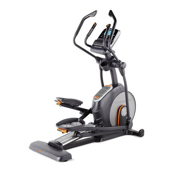
NordicTrack E12.2 User Manual
Hide thumbs
Also See for E12.2:
- Gebruikershandleiding (36 pages) ,
- Manuale d'istruzioni (36 pages) ,
- Manuel de l’utillsateur manual (36 pages)
Advertisement
Table of Contents
- 1 Table of Contents
- 2 Warning Decal Placement
- 3 Important Precautions
- 4 Before You Begin
- 5 Part Identification Chart
- 6 Assembly
- 7 The Chest Heart Rate Monitor
- 8 How to Use the Elliptical
- 9 Maintenance and Troubleshooting
- 10 Exercise Guidelines
- 11 Part List
- 12 Exploded Drawing
- 13 Ordering Replacement Parts
- 14 Recycling Information
- Download this manual
Model No. NTEVEL12913.0
Serial No.
USER'S MANUAL
Write the serial number in the space
above for reference.
Serial Number
Decal
CUSTOMER SERVICE
UNITED KINGDOM
Call: 08457 089 009
From Ireland: 053 92 36102
Website: www.iconsupport.eu
E-mail: csuk@iconeurope.com
Write:
ICON Health & Fitness, Ltd.
c/o HI Group PLC
Express Way
CASTLEFORD
WF10 5QJ
UNITED KINGDOM
AUSTRALIA
Call: 1800 993 770
E-mail: australiacc@iconfitness.com
Write:
ICON Health & Fitness
PO Box 635
WINSTON HILLS NSW 2153
AUSTRALIA
CAUTION
Read all precautions and instruc-
tions in this manual before using
this equipment. Keep this manual
for future reference.
www.iconeurope.com
Advertisement
Table of Contents

Related Manuals for NordicTrack E12.2


Summary of Contents for NordicTrack E12.2
- Page 1 Model No. NTEVEL12913.0 Serial No. USER’S MANUAL Write the serial number in the space above for reference. Serial Number Decal CUSTOMER SERVICE UNITED KINGDOM Call: 08457 089 009 From Ireland: 053 92 36102 Website: www.iconsupport.eu E-mail: csuk@iconeurope.com Write: ICON Health & Fitness, Ltd. c/o HI Group PLC Express Way CASTLEFORD...
-
Page 2: Table Of Contents
If a decal is missing or illegible, see the front cover of this manual and request a free replacement decal. Apply the decal in the location shown. Note: The decal(s) may not be shown at actual size. NORDICTRACK is a registered trademark of ICON IP, Inc. -
Page 3: Important Precautions
IMPORTANT PRECAUTIONS WARNING: To reduce the risk of serious injury, read all important precautions and instructions in this manual and all warnings on your elliptical before using your elliptical. ICON assumes no responsibility for personal injury or property damage sustained by or through the use of this product. -
Page 4: Before You Begin
BEFORE YOU BEGIN Thank you for selecting the revolutionary reading this manual, please see the front cover of this NORDICTRACK E 12.2 elliptical. The E 12.2 elliptical manual. To help us assist you, note the product model ® provides an impressive selection of features designed number and serial number before contacting us. -
Page 5: Part Identification Chart
PART IDENTIFICATION CHART Use the drawings below to identify the small parts needed for assembly. The number in parentheses below each drawing is the key number of the part, from the PART LIST near the end of this manual. The number following the key number is the quantity needed for assembly. -
Page 6: Assembly
ASSEMBLY • Assembly requires two persons. • In addition to the included tool(s), assembly requires the following tools: • Place all parts in a cleared area and remove the one Phillips screwdriver packing materials. Do not dispose of the packing materials until you finish all assembly steps. - Page 7 3. With the help of a second person, place some of the packing materials (not shown) under the rear of the Frame (1). Have the second person hold the Frame to prevent it from tipping while you complete this step. Attach the Rear Stabilizer (2) to the Frame (1) with two M10 x 122mm Screws (104) and two M10 Split Washers (105).
- Page 8 5. Tip: Avoid pinching the wires. Avoid damag- ing the indicated plastic tabs. Set the Upright (4) on the Frame (1). Avoid pinching the wires and avoid Attach the Upright (4) with four M10 x 25mm damaging the tabs Screws (99) and four M10 Split Washers (105). Do not fully tighten the Screws yet.
- Page 9 7. Using a plastic bag to keep your fingers clean, apply some of the included grease to the Pivot Axle (35) and to two 16mm Wave Washers (54). Insert the Pivot Axle (35) through the Upright (4) and center it. Tip: It may be helpful to use a rubber mallet.
- Page 10 9. Untie and discard the wire tie on the Upper Wire (110) and the Fan Extension Wire (146). While a second person holds the Console (7) near the Upright (4), connect the wires on the Console to the Upper Wire (110), to the Fan Extension Wire (146), and to the Sensor Wires (63, 144).
- Page 11 11. Orient the Right Pedal Arm (58) assembly as shown. Apply grease to the axle on the Right Pedal Arm (58). Attach the Right Pedal Arm (58) to the Right Roller Arm (59) with an M8 x 14mm Shoulder Screw (147), a Small Axle Cover (55), and an M8 Washer (97).
- Page 12 13. Orient the Shield Cover (75) assembly as shown. While a second person holds the Shield Cover (75) assembly near the Upright (4), connect the Fan Extension Wire (146) to the Fan Wire (136). Avoid pinching the wires Tip: Avoid pinching the wires. Press the Shield Cover (75) onto the Left and Right Shields (73, 74).
- Page 13 15. Orient the Rear Console Cover (80) as shown. Attach the Rear Console Cover (80) to the Upright (4) with two M4 x 16mm Screws (101). Orient the Front Console Cover (79) as shown. Attach the Front Console Cover (79) around the Upright (4) by pressing it into the Rear Console Cover (80).
- Page 14 17. Identify the Right Upper Body Arm Front Cover (65) and orient it as shown. Attach the Right Upper Body Arm Front Cover (65) to the Right Upper Body Leg (60) with two M4 x 16mm Screws (101). Identify the Right Upper Body Arm Rear Cover (66) and orient it as shown.
-
Page 15: The Chest Heart Rate Monitor
THE CHEST HEART RATE MONITOR HOW TO PUT ON THE HEART RATE MONITOR • Do not expose the heart rate monitor to direct sun- light for extended periods of time; do not expose it to The heart rate temperatures above 122° F (50° C) or below 14° F monitor consists of (-10°... -
Page 16: How To Use The Elliptical
HOW TO USE THE ELLIPTICAL HOW TO PLUG IN THE POWER CORD Follow the steps below to plug in the power cord. This product must be earthed. If it should malfunc- 1. Plug the indicated end of the power cord into the tion or break down, earthing provides a path of least socket on the frame. - Page 17 HOW TO MOVE THE ELLIPTICAL HOW TO ADJUST THE POSITIONS OF THE PEDALS Due to the size and weight of the elliptical, moving it requires two persons. Stand in front of the elliptical, Each pedal can be adjusted to several positions. To hold the upright, and place one foot against one of the adjust each pedal, simply pull the pedal handle out- wheels.
- Page 18 HOW TO EXERCISE ON THE ELLIPTICAL To dismount the elliptical, wait until the pedals come to a complete stop. Note: The elliptical does not have To mount the elliptical, hold the handlebars or the a free wheel; the pedals will continue to move until the flywheel stops.
- Page 19 CONSOLE DIAGRAM FEATURES OF THE CONSOLE wireless network through an optional iFit module. With iFit, you can download personalized workouts, create The advanced console offers an array of features your own workouts, track your workout results, race designed to make your workouts more effective and against other iFit users, and access many other fea- tures.
- Page 20 HOW TO TURN ON THE POWER HOW TO USE THE MANUAL MODE IMPORTANT: If the elliptical has been exposed to 1. Begin pedaling or press any button on the cold temperatures, allow it to warm to room tem- console to turn on the console. perature before turning on the power.
- Page 21 4. Follow your progress with the display. Time—When the manual mode is selected, this display mode will show the elapsed time. When a The display can show the following workout workout is selected, this display mode will show the information: time remaining in the workout.
- Page 22 When a wireless iFit one or two dashes will appear, and then your heart rate will be shown. For the most accurate heart module is connected, rate reading, hold the contacts for at least 15 the wireless symbol at the top of the display seconds.
- Page 23 HOW TO USE AN ONBOARD WORKOUT the profile will begin to flash. If a different resis- tance level, ramp incline level, and/or target rpm is 1. Begin pedaling or press any button on the programmed for the next segment, the resistance console to turn on the console.
- Page 24 HOW TO USE A SET-A-GOAL WORKOUT Note: The calorie goal is an estimate of the number of calories that you will burn during 1. Begin pedaling or press any button on the the workout. The actual number of calories that console to turn on the console.
- Page 25 HOW TO USE AN IFIT WORKOUT To compete in a race that you have previously scheduled, press the Compete button. You must have an iFit module to use an iFit workout. To re-run a recent iFit workout from your sched- To purchase an iFit module at any time, go to ule, first press the Track button.
- Page 26 6. Follow your progress with the display. HOW TO CHANGE CONSOLE SETTINGS See step 4 on page 21. The console features a user mode that allows you to view usage information, select a unit of measurement, The My Trail tab will show a map of the trail you are and adjust the contrast level of the display.
- Page 27 8. Check the status of the iFit module if desired. If no module is connected, the display will show the words NO IFIT MODULE. If no module is con- nected, go to step 10. Press the decrease button to view the iFit sta- tus display.
-
Page 28: Maintenance And Troubleshooting
MAINTENANCE AND TROUBLESHOOTING Inspect and tighten all parts of the elliptical regularly. HOW TO CALIBRATE THE RAMP Replace any worn parts immediately. If the ramp is not functioning properly, the ramp may To clean the elliptical, use a damp cloth and a small need to be calibrated. -
Page 29: Exercise Guidelines
EXERCISE GUIDELINES Burning Fat—To burn fat effectively, you must exer- WARNING: cise at a low intensity level for a sustained period of Before beginning this time. During the first few minutes of exercise, your or any exercise program, consult your physi- body uses carbohydrate calories for energy. - Page 30 SUGGESTED STRETCHES The correct form for several basic stretches is shown at the right. Move slowly as you stretch; never bounce. 1. Toe Touch Stretch Stand with your knees bent slightly and slowly bend forward from your hips. Allow your back and shoulders to relax as you reach down toward your toes as far as possible.
-
Page 31: Part List
PART LIST Model No. NTEVEL12913.0 R0513A Key No. Qty. Description Key No. Qty. Description Frame Roller Rear Stabilizer Right Grip Ramp Large Axle Cover Upright 16mm Wave Washer M4 x 19mm Screw Small Axle Cover Front Stabilizer Roller Arm Bushing Console Arm Bearing Left Handlebar... - Page 32 Key No. Qty. Description Key No. Qty. Description M4 x 16mm Screw Left Pedal Handle M8 Locknut Pedal Pin M6 x 12mm Screw Pedal Spring M10 x 122mm Screw M10 x 140mm Bolt M10 Split Washer M6 Acorn Nut Cover Mount Fan Grill M4 x 48mm Screw Fan Bracket...
-
Page 33: Exploded Drawing
EXPLODED DRAWING A Model No. NTEVEL12913.0 R0513A... - Page 34 EXPLODED DRAWING B Model No. NTEVEL12913.0 R0513A...
- Page 35 EXPLODED DRAWING C Model No. NTEVEL12913.0 R0513A...
-
Page 36: Ordering Replacement Parts
ORDERING REPLACEMENT PARTS To order replacement parts, please see the front cover of this manual. To help us assist you, be prepared to provide the following information when contacting us: • the model number and serial number of the product (see the front cover of this manual) • the name of the product (see the front cover of this manual) • t he key number and description of the replacement part(s) (see the PART LIST and the EXPLODED DRAWING near the end of this manual) RECYCLING INFORMATION This electronic product must not be disposed of in municipal waste.
Need help?
Do you have a question about the E12.2 and is the answer not in the manual?
Questions and answers