Lathem Airtime ATDDC4 Installation & User Manual
Wireless digital wall clock
Hide thumbs
Also See for Airtime ATDDC4:
- Installation & user manual (13 pages) ,
- Installation & user manual (14 pages)
Table of Contents
Advertisement
Quick Links
Advertisement
Table of Contents

Related Manuals for Lathem Airtime ATDDC4


Summary of Contents for Lathem Airtime ATDDC4
- Page 1 Wireless Digital Wall Clock Model ATDDC4 Installation & User’s Guide...
- Page 2 Time Corp. reserves the right to make changes to any products herein to improve reliability, function, or design. Trademark AirTime, Lathem and the Lathem logo are registered trademarks of Lathem Time Corporation. Other product names mentioned in this manual may be trademarks of their respective companies and are hereby acknowledged.
-
Page 3: Clock Operation
Note: It may take up to several minutes for the clock to initially If it becomes necessary to send the product or any defective part to Lathem or any authorized service dealer, the product must be shipped in its original carton or synchronize. -
Page 4: Specifications
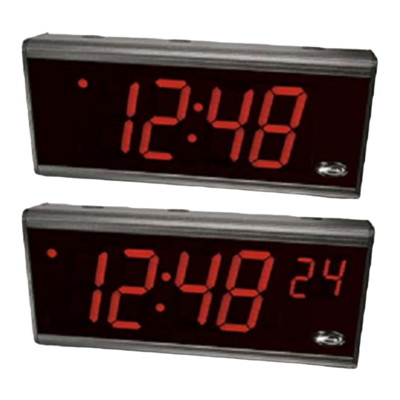
ATDDC4 Series Installation & User’s Guide ATDDC4 Series Installation & User’s Guide Specifications Clock Installation Tools required for mounting the clock: Dimensions 6 3/4" H X 15 1/2" W X 3 1/8" D 17.1 cm H X 39 cm W X 7.9 cm D •... - Page 5 ATDDC4 Series Installation & User’s Guide ATDDC4 Series Installation & User’s Guide To set the display format, use the jumper (J1) located on the back of the circuit board which can be accessed by removing the right side end cap and sliding the circuit board out slightly. Back Side of Circuit Board Jumper J1 On = 12 Hour display...
- Page 6 ATDDC4 Series Installation & User’s Guide ATDDC4 Series Installation & User’s Guide Mounting to a Wall Double Mount - Ceiling After deciding where to mount the clock, make two marks 12" apart Requires optional mounting kit (SAM0626) and horizontal. Note: If mounting near a ceiling, make sure the holes are at least 2 1/4"...
- Page 7 ATDDC4 Series Installation & User’s Guide ATDDC4 Series Installation & User’s Guide Power Connection – Wall Mount 120vAC Electrical Supply can be brought into the ATDDC4 enclosure from any of the six vent-hole positions, from the back, or from either side.
- Page 8 ATDDC4 Series Installation & User’s Guide ATDDC4 Series Installation & User’s Guide Double Mount – Wall Attaching Conduit The ATDDC4 SERIES requires optional mounting kit (SAM0625) The Electrical Supply can be brought into the ATDDC4 enclosure from Tools required for mounting the clock: any of the top three vent-hole positions, from the back, or from either side.
Need help?
Do you have a question about the Airtime ATDDC4 and is the answer not in the manual?
Questions and answers