Table of Contents
Advertisement
Advertisement
Table of Contents

Related Manuals for Lathem PC100-R


Summary of Contents for Lathem PC100-R
- Page 1 PC100 Terminal Installation & User’s Guide...
- Page 2 PayClock, Lathem and the Lathem logo are registered trademarks of Lathem Time Corporation. Other product names mentioned in this manual may be trademarks of their respective companies and are hereby acknowledged. Warning: Changes or modifications to this unit not expressly approved by the party responsible for compliance could void the user’s authority to operate the equipment.
- Page 3 Lathem or an authorized Lathem reseller and any such products are purchased "as is, with all faults." In no event will Lathem be liable for any direct, indirect, special, incidental or consequential damages arising out of or in connection with the delivery, use or inability to use, or performance of this product.
-
Page 5: Table Of Contents
Welcome Mounting the PC100 Connecting to the Computer Connecting the PayClock via RS-232 ... 4 Connecting Terminals via RS-485... 4 Connecting Terminals via RS-485 (Star Configuration) ... 5 Connecting Terminals via RS-485 (Multi-Drop Configuration) ... 6 Using the PC100 Special Badges... 7 Badge #251 –... -
Page 7: Welcome
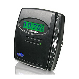
With the PC100 terminal, employees use their plastic ID badges to punch in and out – it’s that simple. Using Lathem software and your computer, the PayClock terminal is the perfect solution for businesses that want to track employee time and automate payroll. -
Page 8: Mounting The Pc100
C H A P T E R 2 Mounting the PC100 Check your package contents to make sure everything is accounted for before starting. Decide where to mount your clock. Keep in mind that the AC adapter plugs into a wall outlet. To mount the clock, you need the following items: Drill with a 5/16”... - Page 9 PC100 Terminal User’s Guide 2. Place the clock onto the mounting bracket Turn your key counter-clockwise in the lock at the clock’s right-middle » section to unlock Align the keyholes on the back of the clock with the studs on the »...
-
Page 10: Connecting To The Computer
PC2000, PC100-R or PC3500 terminals. The PC100 / PC2000 modular port is set up to use with the PC2000 and PC100-R terminals. The PC2500 modular port is set up to use with the PC400 terminals (not currently available). -
Page 11: Connecting Terminals Via Rs-485 (Star Configuration)
PC100 Terminal User’s Guide Use either connection RS485 Power to terminals LED’s RS232 RS232 to PC Connecting Terminals via RS-485 (Star Configuration) A star network connects up to 31 terminals or sync time devices to the computer. You can wire the terminals directly to the SWIFT-485+ or use J- kits (junction boxes). -
Page 12: Connecting Terminals Via Rs-485 (Multi-Drop Configuration)
J-Kit (junction box) and repeat steps 2, 3 & 4 6. See the Cable Wiring Diagrams for detailed connection points For more details or how to supply AC power to the PC100-R from the SWIFT- 485+, see the SWIFT-485+ User’s Guide. -
Page 13: Using The Pc100
C H A P T E R 4 Using the PC100 The base model PC100 clock allows only an RS-232 connection. The PC100-R model allows RS-232 or RS-485 connections; RS-485 connections require the Terminal Manager software add-on. The PC100 has a magnetic stripe badge reader. The magnetic stripe should be on the left side of the badge when swiping. -
Page 14: Badge #253 - Set Baud Rate
PC100 Terminal User’s Guide ♦ PC100 version number ♦ Terminal ID# (ID=49) ♦ Percent full memory (each time you poll the clock, this resets to 0%) ♦ Clock ready status (READY/LOAD LIST) ♦ Baud Rate ♦ 12-Hour or 24-Hour time display format ♦... -
Page 15: Specifications
Ports: RS-232 cable at speeds of 1200, 2400, 4800 and 9600 baud For PC100-R: RS-485 Cat. 3 or Cat. 5 cable (suggested) at speeds of 2400, 4800 and 9600 baud. Up to 4000 feet Certifications: UL; C-UL; FCC Part-15 Class-B; Canada ICES-003 Class-B;... -
Page 16: Cable Wiring Diagrams
PC100 Terminal User’s Guide A P P E N D I X A Cable Wiring Diagrams RS-232 (Computer to PC100) -
Page 17: Rs-485 Multi-Drop
RS-485 Multi-Drop See Fig. A Fig. A – Junction box wiring connect points Some junction boxes have only six connect points instead of eight PC100 Terminal User’s Guide PayClock Be sure to maintain polarity through out the chain 8 points 6 points PayClock PayClock... -
Page 18: Junction Box To Terminal
PC100 Terminal User’s Guide Junction Box to Terminal... -
Page 19: Troubleshooting
A P P E N D I X B Troubleshooting PC100 Description When I swipe a badge, it does not record and the clock does not signal any errors PC100 Terminal User’s Guide Solution Make sure you swiped the badge correctly. - Page 21 INDEX Badges... 7 Baud Rate... 8 Bracket ... See Mounting Bus Configuration... 6 Cable ... 4 Junction Box ... 12 Modem ... 4 Mounting... 1 PC100 ... 2 Multi-Drop Configuration... 6 PC100... 1, 7, 9 PC2000... 4 Punch the Clock ... 1 RS-232 ...
Need help?
Do you have a question about the PC100-R and is the answer not in the manual?
Questions and answers