Table of Contents
Advertisement
Advertisement
Table of Contents

Related Manuals for Lathem PC700


Summary of Contents for Lathem PC700
- Page 2 Cet appariel numerique de la classe A est conforme a la norme NMB-003 du Canada. Lathem Time Corporation 200 Selig Drive, SW, Atlanta, GA 30336 www.lathem.com Copyright © 2017 Lathem Time Corporation. All rights reserved. Revised 04-26-2018 Document number: USG0114A...
-
Page 3: Table Of Contents
Install the PC700 Series Clock ............. 5 PayClock Online Adding a PC700 series clock ............8 Step 1 - Adding the PC700 series clock ........8 Step 2 - Connect the Clock to PayClock Online......9 Changing settings at the Clock ........... 10 How do I change the time zone? .......... - Page 4 Date/Time Setup - Date ............26 Error Log ................... 27 Relay Settings ................28 Test Connection ............... 28 Reset ..................29 Troubleshooting the PC700 Series Clock General Troubleshooting ............30 PC700 Series Troubleshooting ........... 30 Appendix A – Testing the Connection to PayClock Online...
-
Page 5: Welcome
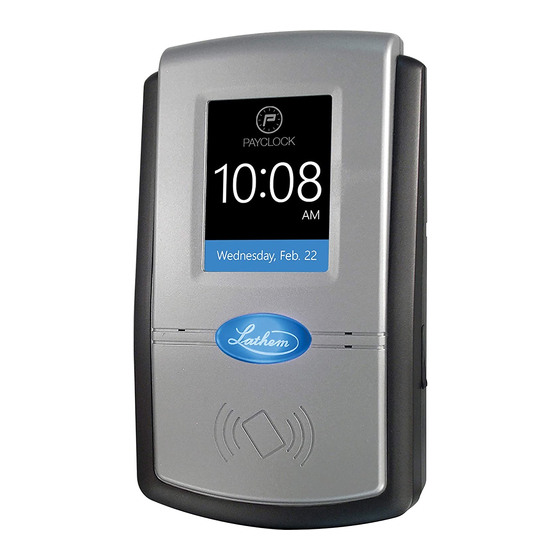
PayClock clocks. With the PC700 clock, employees can use a badge or PIN to punch in and out, view messages or benefit time balances – it’s that simple. In addition, the PC700 contains an on-board relay which can be used to control bells/signaling devices, or security access. - Page 6 IEEE 802.11a/b/g standard. It supports WEP, WPA and Open authentication. • PC700 series Idle Screen - Easy to read time/date screen will display after 2 minutes of inactivity on the clock. • User friendly design - Large easy to read touch-panel.
- Page 7 Troubleshooting For answers to Frequently Asked Questions, refer to the Troubleshooting section of this User Guide. Online and Email Support Lathem.com provides access to numerous support resources. Visit the following link: http://kb.lathem.com for additional help or to submit a question. You should receive a reply within 24 hours.
-
Page 8: Package Contents
Package Contents Please verify that your package includes ALL of the following items. If your package is missing an item, please call our help desk at (800) 224-1877. Recommended Installation Tools 4 • Welcome... -
Page 9: Install The Pc700 Series Clock
Install the PC700 Series Clock Step 1: Select a site to install your clock that will be convenient to employees clocking in and out. When deciding where the clock will be installed, keep in mind that an 115vAC power outlet should be within reach of the mounting location as well as a connection to the network (LAN). - Page 10 Press Network Setup. The Network Setup screen will display. • Press WiFi. The PC700 will check to see if there are any Wi- Fi connections within range and display them in a list. Note: Make sure the WiFi Enabled is set to Yes.
- Page 11 When finished, plug the power adapter into an AC wall outlet. You are now ready to sync the PC700 clock once it is set up in the PayClock Online software...
-
Page 12: Payclock Online
The PayClock Online product is in the cloud and communicates with the clock over the internet. Adding a PC700 series clock Adding a PC700 series clock to PayClock Online is a 2-step process. Add the clock in PayClock Online first and then from the clock connect to the hosted database. -
Page 13: Step 2 - Connect The Clock To Payclock Online
Step 2 - Connect the Clock to PayClock Online The PC700 series clock must be added to PayClock Online before attempting this step. The clock must be powered up and connected to the network with access to the internet. •... -
Page 14: Changing Settings At The Clock
Changing settings at the Clock The default settings that can be changed by the administrator at the clock or the PayClock Online software are: • Time Zone: The time zone is set to Eastern Time. • Daylight Savings Time: Daylight savings is turned on. •... -
Page 15: How Do I Disable Daylight Savings
How do I disable daylight savings? • From the clock touchpad press the Admin button. Enter the administrator password (PIN) and press the Enter button. • The Administrator Main Menu screen will display. • Press Date/Time Setup. The Date Setup screen will display. •... -
Page 16: How Do I Disable Daylight Savings
• The clock will update itself at the next update interval. How do I disable daylight savings? • Log into PayClock Online and go to Clocks>Manage Clocks in the navigation list. • Select the desired clock from the list and click on the Settings tab. -
Page 17: How Do I Disable Badge Entry For All Employees
• Click Save. • The clock will update itself at the next update interval. How do I disable Badge entry for all employees? The clock will display “Not Authorized” if an employee presents a badge. • Log into PayClock Online and go to Clocks>Manage Clocks in the navigation list. -
Page 18: How Do I Disable Transfers For All Employees
How do I disable transfers for all employees? The Transfers Depts. button will not display on the clocks touchpad when Allow Transfers is disabled • Log into PayClock Online and go to Clocks>Manage Clocks in the navigation list. • Select the desired clock from the list and click on the Settings tab. -
Page 19: Using The Pc700 Series Clock
Notice: The clock utilizes an internal antenna to read the employee badges. Make sure these badges are stored at least 6” away from the clock when not in use to avoid accidental badge reads. Using the PC700 Series Clock • 15... -
Page 20: Pc700 Series Clock Idle Screen
• Press the Transfer Depts. button on the touch-pad of the clock. • Move the badge over the badge reader symbol below the illuminated oval target area on the front of the clock. 16 • Using the PC700 Series Clock... -
Page 21: Amount Entries
Clocking IN/Out • Press the Clock In/Out button on the touch-pad of the clock. • The Enter PIN screen will display. Using the numeric key pad enter the employee’s PIN number and press Enter. Using the PC700 Series Clock • 17... -
Page 22: Department Transfers
The Enter PIN screen will display. Using the numeric key pad enter the employee’s PIN number and press Enter. • A confirmation beep will sound and the employee’s grand totals for the pay period and any benefit time will display. 18 • Using the PC700 Series Clock... -
Page 23: Supervisor Transactions
Adding Punches This supervisor function requires that the clock have an active connection to the internet. At the clock press the Supervisor button. The Enter PIN screen will display. Using the PC700 Series Clock • 19... -
Page 24: Viewing Totals
• When finished press the button to return to the default screen. Send Message At the clock press the Supervisor button. The Enter PIN screen will display. 20 • Using the PC700 Series Clock... -
Page 25: Override Lockout
Settings - Set/Change PIN This supervisor function requires that the clock have an active connection to the internet. At the clock press the Supervisor button. The Enter PIN screen will display. Using the PC700 Series Clock • 21... -
Page 26: Settings - View/Assign Badge
You know PIN entry is disabled when there is a check in the box. • When finished press the button to return to the default screen. Settings - View/Assign Badge This supervisor function requires that the clock have an active connection to the internet. 22 • Using the PC700 Series Clock... -
Page 27: Administrator Functions
To enter administrator mode at the clock, press the Admin button. The Enter PIN screen will display. • Using the numeric key pad enter the administrator PIN number and press Enter. Using the PC700 Series Clock • 23... -
Page 28: Sync Now
PayClock Online. To enter administrator mode, at the clock press the Admin button. The Enter PIN screen will display. • Using the numeric key pad enter the administrator PIN number and press Enter. 24 • Using the PC700 Series Clock... - Page 29 Press Network Setup. The Network Setup screen will display. • Press WiFi. The PC700 will check to see if there are any Wi- Fi connections within range and display them in a list. Note: Make sure the WiFi Enabled is set to Yes.
-
Page 30: Date/Time Setup - Date
The Enter PIN screen will display. • Using the numeric key pad enter the administrator PIN number and press Enter. • The Administrator Main Menu screen will display. • Press Date/Time Setup. The Date Setup screen will display. 26 • Using the PC700 Series Clock... -
Page 31: Error Log
Use the left or right arrow keys to scroll through any errors. • When finished press the center of the screen and then press the back button until you have returned to the default screen. Using the PC700 Series Clock • 27... -
Page 32: Relay Settings
To enter into administrator mode at the clock press the Admin button. The Enter PIN screen will display. • Using the numeric key pad enter the administrator PIN number and press Enter. • The Administrator Main Menu screen will display. 28 • Using the PC700 Series Clock... -
Page 33: Reset
WARNING: Use caution when selecting this menu item. This menu item will reset the entire clock to the manufacturer default settings. All settings, administrators, supervisors, employees and data will be cleared; you cannot recover this information. Using the PC700 Series Clock • 29... -
Page 34: Troubleshooting The Pc700 Series Clock
IT person make sure there aren’t any issues with the network. Issue Resolution If your terminal isn’t connecting The terminal isn’t connecting to to PayClock Online, use the Test PayClock Online. Connection button. See Appendix A for details. 30 • Troubleshooting the PC700 Series Clock... - Page 35 Admin button and enter 528436 then press Enter. Press OK to the confirmation message “Idle Screen Mode: Off”. Note: to reactivate the idle screen simply enter the 528436 code again. Troubleshooting the PC700 Series Clock • 31...
-
Page 36: Appendix A - Testing The Connection To Payclock Online
IT department or someone familiar with your network if you have connection issues. The PC700 series clock has a function that will allow the user to test the connection to PayClock Online. This test will verify the internet connection, access to the internet through the required ports and the connection to the PayClock Online service. - Page 37 Test 2 – Ports used by the clock will tested. Pass = The test cycle will move to the PayClock Online service test. Fail – What should I do if this test fails? • Open the listed port(s) to traffic. •...
-
Page 38: Appendix B - Bell Relay Connections
Appendix B - Bell Relay Connections The PC700 has a built-in relay that can control bells or door access. Relay Specifications • Type: Dry Contact Closure • Rating: 2 amps at 24VDC or 120VAC • Contacts: NO-Normally Open, COM Common, NC Normally... - Page 39 Connect the wires from the signaling device to the screw clocks. Plug the clock connector into the socket on the PC700. Only one (1) wire should be inserted into the clock block positions NO and COM, all wire splices should be done externally. See the following diagrams for details.
- Page 40 PC700 PC700 PC700 36 • Appendix B - Bell Relay Connections...
- Page 41 PC700 PC700 Appendix B - Bell Relay Connections • 37...
- Page 42 PC700 PC700 Important! Connecting the PC700 to a public address (PA) system requires the use of an external Tone Generator. Contact your PA supplier to acquire an appropriate Tone Generator for your system. 38 • Appendix B - Bell Relay Connections...
-
Page 43: Appendix C - Access Relay Connections
Unplug the relay screw clock connector. Connect the wires from the door access device to the screw clocks. Plug the clock connector into the socket on the PC700. Only one (1) wire should be inserted into the clock block positions NO and COM, all wire splices should be done externally. - Page 44 Wiring for Door Access Control System PC700 PC700 40 • Appendix C - Access Relay Connections...
-
Page 45: Appendix D - Add/Edit/Delete Bell Events
Adding a Bell Event • From the PC700 touchpad press the Admin button. Enter the administrator PIN and press Enter. • From the Administrator Main Menu press Relay Settings. - Page 46 Editing a Bell Event • From the PC700 touchpad press the Admin button. Enter the administrator PIN and press Enter. • From the Administrator Main Menu press Relay Settings. • The Relay Settings screen will display. • Press Schedule under Signal Events. The Signal Event Schedule screen will display with all the schedule events.
-
Page 47: Glossary Of Terms
Glossary of Terms Administrator The PC700 series clock has one administrator, the administrator function allows you review the device information, set up the network communications, set the time / date, review an error log and reset the clock to the factory defaults. -
Page 49: Index
Install the PC700 Series Index Terminal 5 Package Contents 4 PC700 Series Terminal Idle Screen 16 Add the terminal from PayClock 8 Supervisor Transactions 19 Administrator Functions 23 Sync Now 24 Changing settings from Troubleshooting 30 PayClock Online 11 Using the PC700 Series... - Page 50 Lathem or from an authorized Lathem reseller. The conditions of this warranty and the extent of the responsibility of Lathem Time Corporation (“Lathem”) under this warranty are listed below.
Need help?
Do you have a question about the PC700 and is the answer not in the manual?
Questions and answers