Lantronix XPort User Manual
Lantronix technical support user guide xport
Hide thumbs
Also See for XPort:
- User manual (123 pages) ,
- Integration manual (24 pages) ,
- Quick start manual (10 pages)
Table of Contents
Advertisement
Quick Links
Download this manual
See also:
User Manual
Advertisement
Table of Contents

Subscribe to Our Youtube Channel
Related Manuals for Lantronix XPort


Summary of Contents for Lantronix XPort
- Page 1 XPort™ User Guide Part Number 900-270 Revision E August 2004...
-
Page 2: Copyright And Trademark
Copyright and Trademark © 2004, Lantronix. All rights reserved. No part of the contents of this book may be transmitted or reproduced in any form or by any means without the written permission of Lantronix. Printed in the United States of America. -
Page 3: Disclaimer And Revisions
XPort OEM firmware license agreement. Date Rev. 11/03 4/04 8/04 If you use a previous version of the firmware, go to the Lantronix FTP site at ftp://ftp.lantronix.com/pub XPort™ User Guide Comments Initial release Updates. Revised for v.1.6 of the firmware. -
Page 4: Table Of Contents
Dedicated Connection ___________________________________________________ 18 Flush Mode Input Buffer __________________________________________________ 18 Packing Algorithm ______________________________________________________ 19 Additional Settings ______________________________________________________ 19 Factory Settings ____________________________________________________ 20 Update Settings ____________________________________________________ 20 4: Using Setup Mode for Configuration Accessing Setup Mode ______________________________________________ 21 XPort™ User Guide... - Page 5 DHCP Name ___________________________________________________________ 25 Channel 1 Configuration (Serial Port Parameters) _________________________ 25 Baudrate ______________________________________________________________ 25 I/F (Interface) Mode _____________________________________________________ 26 I/F Mode: XPort-485 only _________________________________________________ 26 Flow__________________________________________________________________ 27 Port Number ___________________________________________________________ 27 Connect Mode__________________________________________________________ 28 Remote IP Address ______________________________________________________ 33...
- Page 6 7: Monitoring the Network Entering Monitor Mode via the Serial Port ____________________________________ 52 Entering Monitor Mode via the Network Port __________________________________ 52 Monitor Mode Commands ________________________________________________ 52 8: Troubleshooting Problems and Error Messages ________________________________________ 54 Technical Support __________________________________________________ 57 XPort™ User Guide...
-
Page 7: 1: Using This Guide
This guide provides the information needed to configure, use and update the XPort™ and is intended for software developers and system integrators who are embedding the XPort in their designs. The information in this guide is relevant to XPort with firmware version 1.5 and higher. -
Page 8: Additional Documentation
Additional Documentation The following guides are available on the product CD and the Lantronix web site (www.lantronix.com). XPort Quick Start XPort Integration Guide Com Port Redirector User Guide Web Enabling Your Device Server XPort™ User Guide Provides the steps for getting the XPort evaluation board up and running. -
Page 9: 2: Introduction
Has three programmable I/O pins used to monitor or control attached devices. Applications The XPort device server connects serial devices such as those listed below to Ethernet networks using the IP protocol family. ATM machines CNC controllers... -
Page 10: Protocol Support
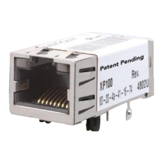
The hardware address is also referred to as the Ethernet address or the MAC address. The first three bytes of the Ethernet address are fixed and read 00-20-4A, identifying the unit as a Lantronix product. The fourth, fifth, and sixth bytes are unique numbers assigned to each unit. -
Page 11: Assigning An Ip Address
(GUI) on a PC attached to a network. (See 3:Getting Started.) Serial Port Login: With this method, you connect a terminal or a PC running a terminal emulation program to the unit’s serial port (CH 1). (See 4:Using Setup Mode.) XPort™ User Guide... -
Page 12: 3: Getting Started
3: Getting Started This chapter covers the steps for getting the XPort device server online and working. Required Information Hardware Address You need to know the unit’s hardware address (also known as MAC address), which is on the product label. It is in the format: 00-20-4a-XX-XX-XX, where the XXs are unique numbers assigned to the product. -
Page 13: Assigning An Ip Address
If the unit already has an IP address (e.g., DHCP has assigned an IP address), click the Search icon and select the unit from the list of Lantronix device servers on the local network. 2. Click the Assign IP icon 3. -
Page 14: Using Web-Manager To Configure The Unit
You can change the configuration at any time. The unit performs a reset after you change and store the configuration. In this chapter, we describe how you can configure the XPort using Web-Manager, Lantronix’s browser-based configuration tool. (For information on using Setup Mode,... -
Page 15: Unit Configuration Settings
Use Setup Mode to configure e-mail, expert settings, and security settings. Use DeviceInstaller for the configurable pins’ settings. Unit Configuration Settings Click the Unit Configuration button to display the following page: XPort™ User Guide 4:Using Setup Mode, explains the configuration settings in... -
Page 16: Server Properties
Note: The following examples represent typical web pages. See the Lantronix web site for the latest version. Server Properties Click the Server Properties button to display the following page: Change the server properties by editing any of the fields. Holding the cursor over a field displays a Help message for that field. -
Page 17: Port Properties
Speed XPort™ User Guide RS232 Note: RS-232 is the only available option for XPort Device Server versions XP1001000-01 & XP1001000-03. RS-422/485 is an additional option for XP1004000-03 (XPort-485). 300, 600, 1200, 2400, 4800, 9600, 19200, 38400, 57600, 115200, and 230400... -
Page 18: Connect Mode Settings
Dedicated Connection Remote IP Address Remote Port Local Port Flush Mode Input Buffer XPort™ User Guide the baud rates 460800 and 921600 bps (see High CPU Performance mode on page 39) 8, 7 None, Even, Odd None, XON/XOFF, XON/XOFF Pass Characters to Host, CTS/RTS... -
Page 19: Packing Algorithm
Check for CTRL-D to Disconnect Port Password Telnet Mode Inactivity Timeout Inactivity Timer Port Password XPort™ User Guide Enable, Disable Enable, Disable Enable, Disable Enable, Disable Packing Interval 12 ms, Interval 52 ms, Interval 250 ms, Interval 5000 ms None, One, Two... -
Page 20: Factory Settings
Click the Factory Settings button to set the device server back to the factory default settings. For details see page Update Settings Click the Update Settings button to send all changed settings to the device server. XPort™ User Guide on page 43. Factory Defaults... -
Page 21: 4: Using Setup Mode For Configuration
IP address, and 9999 is the unit’s fixed network configuration port number: Note: Be sure to include a space between the IP address and 9999. 2. Click OK. The following information displays. XPort™ User Guide telnet x.x.x.x 9999 Figure 4-1. MAC Address 3:Getting Started,... -
Page 22: Using The Serial Port
3. At this point, the screen display is the same as when you use a Telnet connection. To continue, go to step The following figure shows all of the configuration parameters. The remainder of this chapter describes each parameter in detail. XPort™ User Guide Figure 4-2 Setup Menu Options Your choice Using a Telnet Connection... - Page 23 4: Using Setup Mode for Configuration Figure 4-3 Setup Mode Configuration Parameters XPort™ User Guide...
-
Page 24: Server Configuration (Network Configuration)
4 characters. An enhanced password setting (for Telnet access only) of 16 characters is available under Security Settings. Note: You don’t need a password to access the Setup Mode window via a serial connection. XPort™ User Guide Figure 4-4. Server Configuration Parameters Host Bits Netmask 255.0.0.0 255.255.0.0... -
Page 25: Dhcp Name
The unit and attached serial device, such as a modem, must agree on a speed or baud rate to use for the serial connection. Valid baud rates are 300, 600, 1200, 2400, XPort™ User Guide Figure 4-5. Custom DHCP Name... -
Page 26: I/F (Interface) Mode
4800, 9600 (default), 19200, 38400, 57600, 115200, and 230400 bits per second. XPort-03 and greater units also support high-performance baud rates of 460800, and 921600 bits per second (see I/F (Interface) Mode The Interface (I/F) Mode is a bit-coded byte entered in hexadecimal notation. -
Page 27: Flow
Only use the automatic port increment feature to initiate a connection using TCP. Set the port to a non-zero value when the unit is in a passive mode or when you are using UDP instead of TCP. XPort™ User Guide Table 4-5. Flow Control Options Table 4-6. Reserved Port Numbers... -
Page 28: Connect Mode
Incoming Connection Never Accept Incoming Accept with DTR Active Always Accept XPort™ User Guide Table 4-7. Connect Mode Options Rejects all external connection attempts. Accepts external connection requests only when the DTR input is asserted. Cannot be used with Modem Mode. - Page 29 Table 4-10. Manual Connection Address Example Command String C121.2.4.5/1 C28.10/12 XPort™ User Guide A single character is transmitted to the serial port when there is a change in connection state: C = connected, D = disconnected, N = host unreachable.
- Page 30 Hostlist Retrycounter Hostlist Retrytimeout DisConnMode (00) ? FlushMode XPort™ User Guide Result if remote IP is 129.1.2.3 and remote port is 1234 Connects to 129.1.28.10, port 12; enters Monitor Mode If you enable autostart, the unit automatically connects to the remote IP address and remote port specified when the firmware starts.
- Page 31 3. After completing the hostlist, repeat the previous step if necessary to edit the hostlist again. 4. For Retrycounter, enter the number of times the Lantronix unit should try to make a good network connection to a hostlist entry that it has successfully ARPed.
- Page 32 No serial data is received for one second after the last + character. At this time, the unit responds affirmatively per the selected echo/response mode. XPort™ User Guide The unit echoes modem commands and responds to a command with a message string shown in the table below.
-
Page 33: Remote Ip Address
You must set the remote TCP port number for the unit to make outgoing connections. This parameter defines the port number on the target host to which a connection is attempted. XPort™ User Guide Table 4-12. Modem Mode Commands Function Makes a connection to an IP address (x.x.x.x) and a remote port... -
Page 34: Disconnmode
State LED off with connection Disconnect with EOT (^D) (1) The XPort sends the "Terminal Type" upon an outgoing connection. (2) A password is required for a connection to the serial port from the network. (3) The TCP connection closes even if the remote site does not acknowledge the disconnection. -
Page 35: Pack Control
Pack control settings are enabled in Flush Mode. Set this value to 00 if you do not need specific functions. Option Packing Interval Interval: 12ms Interval: 52ms Interval: 250ms Interval: 5sec Trailing Characters None Send Characters 2-Byte Send Character Sequence Send Immediately After Send chars XPort™ User Guide 4-15. Pack Control Options... -
Page 36: Disconntime (Inactivity Timeout)
This parameter appears only if the channel (port) password option is enabled in Disconnect Mode. If the option is enabled, you can set a password on the serial port. XPort™ User Guide Packing Interval defines how long the unit should wait before In some applications, CRC, Checksum, or other trailing on page 35). -
Page 37: E-Mail Settings
E-mail setup requires you to set up the e-mail server location as follows: The IP address in decimal-dot notation. Mail server The user name used by the XPort to send e-mail messages. Unit The domain name of your e-mail server. -
Page 38: Trigger Setup
If a single trigger event stays asserted, then the unit sends an e-mail message at this time interval. (45) (600) (Disabled) applies to XPort-03 and greater only (Enabled) (80) (25) -
Page 39: Tcp Keepalive Time In Seconds
(1-600) the unit will wait before timing out this table. High CPU Performance mode This option applies to XPort-03 and greater units only. It allows you to increase the CPU performance and utilize the higher baud rates on the serial interface (i.e. -
Page 40: Security Settings
This setting defaults to the N (No) option. The Y (Yes) option disables access to Setup Mode by Telnet (port 9999). It only allows access locally via the web pages and the serial port of the unit. XPort™ User Guide... -
Page 41: Disable Tftp Firmware Upgrade
Enable Encryption This option displays only if you purchased the encrypted version of the Lantronix XPort. You can enable or disable (default) Rijndael encryption. Rijndael is the block cipher algorithm recently chosen by the National Institute of Science and Technology (NIST) as the Advanced Encryption Standard (AES) to be used by the US government. -
Page 42: Encryption Tutorial
The XPort uses standard AES encryption protocols. To communicate successfully, products and applications on the peer side must use the same protocols and the same shared key as the XPort. To ease the development process, Lantronix provides an AES encryption DLL for Windows and protocol source code samples. -
Page 43: Enable Enhanced Password
Telnet and Web Page access. Disable Port 77F0 (Hex) Port 77F0 is a setting that allows a custom application to query or set the three XPort configurable pins when they are functioning as general purpose I/O (GPIO). You may want to disable this capability for security purposes. -
Page 44: Expert Settings Defaults
Expert Settings Defaults TCP keepalive ARP cache timeout High CPU performance mode (XPort-03 or greater only) HTTP port number SMTP port number Security Settings Defaults SNMP SNMP community name Telnet setup TFTP download Port 77FEh Web Server ECHO Encryption Enhanced password... -
Page 45: 5: Gpio Interface
5: GPIO Interface Configurable Pins The XPort has three pins (CP1-3) that you can configure for General Purpose I/O (GPIO). Note: You can also configure the pins for serial port control lines, such as CTS, RTS, DTR, and DCD, and diagnostic outputs to LED, using DeviceInstaller. -
Page 46: Guidelines
There is no Set functions command. Since the pin’s function depends on the hardware in which the XPort is embedded, that configuration is only allowed via 77FE. Settings changed by any of the Set commands are not stored and are lost when the unit is powered down or rebooted. - Page 47 Bit X Response: 1 parameter Bytes 1-4: The updated directions XPort™ User Guide 1 means general purpose I/O available to the user. 0 means dedicated function (e.g., serial flow control, diagnostics) for configurable pin X. 1 means GPIO X is an output.
-
Page 48: Examples
Examples Example 1: PC sends command 1 to find out which configurable pins are available as GPIO. PC -> XPort: 10h, 00h, 00h, 00h, 00h, 00h, 00h, 00h, 00h XPort -> PC: 10h, 03h, 00h, 00h, 00h Command details: 10h = command 10h... - Page 49 0 is 1 → GPIO0 = 1 bit 1 is 0 → GPIO1 = 0 bit 2 is 1 → GPIO2 = 1 The other bits are ignored because there are only three configurable pins on the XPort. XPort™ User Guide...
-
Page 50: 6: Updating Firmware
DeviceInstaller (the preferred way), via TFTP, or via the serial port using DeviceInstaller. You can also update the unit's internal Web interface (*.COB) via TFTP or DeviceInstaller. Here are typical names for those files. Check the Lantronix web site for the latest versions and release notes. ROM File XPTEXE16.ROM... -
Page 51: Recovering The Firmware Using The Serial Port And Deviceinstaller
5. For Firmware File, click the Browse button and go to the location where the firmware file resides. Note: Make sure the XPort on which you are recovering firmware is connected to this selected port on your PC. 6. Click OK to download the file. -
Page 52: 7: Monitoring The Network
(xxx.xxx.xxx.xxx). If you enter the IP address, the command is applied to another unit with that IP address. If you do not enter the IP address, the command is executed locally. Note: All commands must be in capital letters. XPort™ User Guide on page 22). - Page 53 Entering any of the commands listed above generates one of the following command response codes: Response 0> 1> 2> 8> 9> XPort™ User Guide Table 7-1. Monitor Mode Commands Command Name Function Version Queries software header record (16 bytes) of unit with IP address x.x.x.x. Get Configuration Gets configuration of unit with IP address x.x.x.x as...
-
Page 54: 8: Troubleshooting
This chapter discusses how you can diagnose and fix errors quickly without having to contact a dealer or Lantronix. It helps to connect a terminal to the serial port while diagnosing an error to view summary messages that may be displayed. When troubleshooting, always ensure that the physical connections (power cable, network cable, and serial cable) are secure. - Page 55 You can ping the device server, but not Telnet to the device server on port 9999. XPort™ User Guide Reason Solution The IP address you are trying to Confirm that your PC has an IP...
- Page 56 When connecting to the Web- Manager within the device server, the No Connection With The Device Server message displays. XPort™ User Guide Reason Solution If you are sure that the serial port You can check to see whether setting is correct, then you may...
-
Page 57: Technical Support
If you are experiencing an error that is not described in this user guide, or if you are unable to fix the error, you may: Check our online knowledge base at http://www.lantronix.com/support. Contact Technical Support in the US: Phone: 800-422-7044 (US only) or 949-453-7198...
Need help?
Do you have a question about the XPort and is the answer not in the manual?
Questions and answers