
Related Manuals for Lantronix Spider


Summary of Contents for Lantronix Spider
- Page 1 Spider™ and SpiderDuo® KVM-over-IP Devices User Guide Part Number 900-495 Revision G November 2013...
-
Page 2: Copyright And Trademark
Copyright and Trademark © 2013 Lantronix, Inc. All rights reserved. No part of the contents of this book may be transmitted or reproduced in any form or by any means without the written permission of Lantronix. Lantronix and SpiderDuo are registered trademarks of Lantronix, Inc. in the United States and other countries. -
Page 3: Disclaimer And Revisions
The user is cautioned that changes and modifications made to the equipment without approval of the manufacturer could void the user’s authority to operate this equipment. Changes or modifications to this device not explicitly approved by Lantronix will voids the user's authority to operate the device. -
Page 4: Table Of Contents
Video Resolutions and Refresh Rates Configuration ___________________________ 31 Mouse-to-Cursor Synchronization _________________________________________ 31 Telnet/SSH Connections to Serial Ports _____________________________________ 32 Cable Connections for KVM and USB ______________________________________ 32 Device Failure or Cable Break in the Daisy Chain __________________________32 Spider™ and SpiderDuo® KVM-over-IP Device User Guide... - Page 5 Screen Display Adjustments ______________________________________________ 50 Fast Sync and Intelligent Sync ____________________________________________ 50 Single and Double Mouse Modes __________________________________________ 50 Local Cursor __________________________________________________________ 50 Optimizing Video __________________________________________________________ 51 Auto and Manual Video Adjustment ________________________________________ 51 Spider™ and SpiderDuo® KVM-over-IP Device User Guide...
- Page 6 Key Release Timeout ___________________________________________________ 66 Country Code _________________________________________________________ 66 USB Mouse Type ______________________________________________________ 67 Mouse Speed _________________________________________________________ 67 Video ___________________________________________________________________ 68 Virtual Media _____________________________________________________________ 69 Virtual Media Active Image _______________________________________________70 Drive Redirection ______________________________________________________ 70 Spider™ and SpiderDuo® KVM-over-IP Device User Guide...
- Page 7 SNMP __________________________________________________________________ 90 KVM Search _____________________________________________________________ 92 Power Management _______________________________________________________ 93 SpiderDuo Power Control Unit ____________________________________________ 94 Wake-On LAN ________________________________________________________ 94 Enable WOL __________________________________________________________ 95 Remove Entries, Reset to Defaults, or Reset _________________________________ 95 Spider™ and SpiderDuo® KVM-over-IP Device User Guide...
- Page 8 Step 1 – Prepare the VM Server _____________________________________________ 122 Step 2 – Enable Virtual Media ______________________________________________123 Step 3 – Use the Virtual Media ______________________________________________125 Appendix C: Supported Resolutions and Refresh Rates Appendix D: Mounting Bracket Kit Spider™ and SpiderDuo® KVM-over-IP Device User Guide...
- Page 9 Power Plug _____________________________________________________________ 130 Input Supply ____________________________________________________________ 130 Grounding ______________________________________________________________ 130 Fuses _________________________________________________________________ 130 Appendix F: Technical Support Technical Support US __________________________________________________ 131 Technical Support Europe, Middle East, Africa ______________________________ 131 Appendix G: Compliance Spider™ and SpiderDuo® KVM-over-IP Device User Guide...
-
Page 10: List Of Figures
Figure 2-5 SpiderDuo PS/2 Cable Dimensions__________________________________________ 21 Figure 2-6 SpiderDuo USB Cable Dimensions __________________________________________ 22 Figure 2-8 Spider Family Product Information Label______________________________________ 24 Figure 3-1 Spider RS-232 Serial Port and Pinouts _______________________________________ 26 Figure 3-3 Spider Login Window_____________________________________________________ 27 Figure 3-4 Spider Prompts _________________________________________________________ 27... - Page 11 Figure 10-3 Configuration Page _____________________________________________________ 98 Figure 10-4 Update Firmware Page __________________________________________________ 99 Figure 10-5 Event Log Page _______________________________________________________ 100 Figure 10-6 Unit Reset Page_______________________________________________________ 101 Figure 10-7 iGoogle Gadget Page __________________________________________________ 103 Spider™ and SpiderDuo® KVM-over-IP Device User Guide...
-
Page 12: List Of Tables
List of Tables Table 1-1 Chapter/Appendix and Summary ____________________________________________ 13 Table 1-2 Conventions Used in This Book _____________________________________________ 14 Table 2-3 Spider Technical Specifications _____________________________________________ 19 Table 2-7 SpiderDuo Technical Specifications _________________________________________ 22 Table 3-2 Spider LEDs ____________________________________________________________ 27 Table 4-3 SpiderDuo Indicator LEDs _________________________________________________ 36... -
Page 13: 1: About This Guide
About This Guide This guide describes how to install, configure, use, and update the Lantronix® Spider™ and SpiderDuo® distributed keyboard, video, and mouse (KVM) -over-IP devices. It describes how to remotely and securely provide monitoring and control of one target computer system by one or more remote users. -
Page 14: Conventions
Appendix C: Supported Resolutions and Lists the resolutions and refresh rates that are supported. Refresh Rates Appendix D: Mounting Bracket Kit Describes how to mount the Spider or SpiderDuo Device in a rack. Appendix E: PCU Safety Information Provides PCU safety information. -
Page 15: Additional Documentation
Visit the Lantronix web site at www.lantronix.com/support/documentation for the latest documentation and the following additional documentation: Spider View User Guide—Details instructions on using the Spider View utility. Spider Quick Start Guide—Provides an overview of using the Spider device. ... -
Page 16: 2: Overview
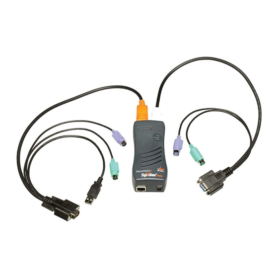
Features The Spider device is unique in that it is low-enough in power consumption to be powered from the attached server. The color-coded cable plugs for the keyboard, mouse, USB port and video are designed to plug directly into the target server. An optional external AC/DC power supply is available. -
Page 17: Functionality
The Spider device supports up to 1600 x 1200 resolution at 60 Hz if its hardware revision is G22, G23, E21 or higher. If the Spider device hardware is an earlier revision, it will only support resolutions up to 1280 x 1024 at 60 Hz. The hardware revision number... -
Page 18: Figure 2-1 Spider System Configuration
2: Overview Figure 2-1 Spider System Configuration Figure 2-2 Spider Cable Dimensions Spider™ and SpiderDuo® KVM-over-IP Device User Guide... -
Page 19: Technical Specifications
The Spider device supports up to 1600 x 1200 resolution at 60 Hz if its hardware revision is G22, G23, E21 or higher. If the Spider device hardware is an earlier revision, it will only support up to 1280 x 1024 resolution at 60 Hz. -
Page 20: Spiderduo Overview
Uses Java KVM console to accept keystrokes and mouse movements on the user system; recognize those intended for the target computer; transmit the keystrokes and mouse movements; and emulate a physically attached keyboard and mouse. Spider™ and SpiderDuo® KVM-over-IP Device User Guide... -
Page 21: System Configuration And Cables
Figure 2-5 shows the PS/2 cable dimensions, and Figure 2-6 shows the USB cable dimensions. Figure 2-4 SpiderDuo System Configuration Figure 2-5 shows the PS/2 cable dimensions. Figure 2-5 SpiderDuo PS/2 Cable Dimensions Spider™ and SpiderDuo® KVM-over-IP Device User Guide... -
Page 22: Technical Specifications
Client System Requirements Internet Explorer 6.0+, Netscape 5.0+, Mozilla FireFox 1.0+, Safari 2.0+ PIII Processor equivalent or better (recommended) Sun Java 2 Runtime Environment Telnet/SSH client for command line (CLI) access Spider™ and SpiderDuo® KVM-over-IP Device User Guide... -
Page 23: Product Information Label
PS/2: 278g (9.80 oz) Shipping Weight 1.5 kg (3.3 lbs) Product Information Label The Product Information Label on the back of the Spider family units contains the following information: Bar code Serial number Revision number ... -
Page 24: Figure 2-8 Spider Family Product Information Label
2: Overview Figure 2-8 Spider Family Product Information Label Spider™ and SpiderDuo® KVM-over-IP Device User Guide... -
Page 25: 3: Installing The Spider Device
Installing the Spider Device This chapter describes how to install the Lantronix Spider KVM-over-IP device. It contains the following sections: Package Contents Installing the Spider Detector Installation and IP Address Reset Target Computer Setup Client Server Setup ... -
Page 26: Figure 3-1 Spider Rs-232 Serial Port And Pinouts
Ethernet connection to access the administration user interface. Tag each Spider device with its IP address or write it on the serial number label on the bottom. -
Page 27: Figure 3-3 Spider Login Window
3: Installing the Spider Device 4. The Pwr2 LED illuminates blue and the SysOK LED flashes green to indicate that the Spider device is booting. Bootup should complete within one minute. The SysOK LED stops flashing and remains illuminated. If you use the external power supply to boot, Pwr1 illuminates blue. -
Page 28: Detector Installation And Ip Address Reset
Figure 3-5 Spider RJ45 Ethernet and Cascade Ports Detector Installation and IP Address Reset The initial IP address gets assigned during bootup of the Spider device. To change it, use the Detector application. You can download Detector from Lantronix at http://www.lantronix.com/... -
Page 29: Figure 3-7 Detector Device List Window
5. Before searching for devices, go to the Timeout drop-down menu in the toolbar. Change the milliseconds for the search by clicking the number in the Timeout drop=down menu. The default is 3000. 6. Click the Search icon . A list of Lantronix Ethernet devices on the network displays as shown in Figure 3-7. -
Page 30: Target Computer Setup
8. Enter an unique and valid IP Address on your network and in the same subnet as your PC. There is no default. 9. Enter the subnet mask that is the network segment connected to the Spider device. To accept the default, leave blank. -
Page 31: Video Resolutions And Refresh Rates Configuration
The Spider device recognizes video resolutions on the target computer up to a maximum of 1600 x 1200 at 60 Hz if its hardware revision G22, G23, E21 or higher. If the Spider hardware is an earlier revision, it will only support up to 1280 x 1024 resolution at 60 Hz. For the complete list of... -
Page 32: Telnet/Ssh Connections To Serial Ports
Connections for KVM and USB are integrated into the Spider device. Do not use extension cables. Plug the Spider device directly into the ports on the host server. If using the Spider serial port, plug the cable into the COM port on the server. -
Page 33: Client Server Setup
Pwr1 indicates that power is available only on the first USB port. Pwr2 indicates that power is available on the second USB port or the PS/2 port. When both LEDs are lit, the Spider device is powered and can boot. -
Page 34: 4: Installing The Spiderduo Device
Installing the SpiderDuo Device This chapter describes how to install the Lantronix SpiderDuo device. It contains the following sections: Package Contents Installing the SpiderDuo Detector Installation and IP Address Reset Target Computer Setup Client Server Setup ... -
Page 35: Figure 4-1 Spiderduo Rj45 Port And Power Connector
The blue LED SysOK lluminates and flashes to indicate that the SpiderDuo device is booting up. Bootup completes within approximately one minute. The SysOK LED stops flashing and remains illuminated. Connections for video, USB, and keyboard/mouse are integrated into the SpiderDuo device. Spider™ and SpiderDuo® KVM-over-IP Device User Guide... -
Page 36: Figure 4-2 Spiderduo Local Kvm, Usb, Computer Input And Serial Ports
8. Type Enter, to accept the changes. The system takes about 20 seconds to complete. Type Enter once again at the prompt to display the updated IP address. 9. Plug an Ethernet cable connected to your network into the Ethernet port. The Link LED illuminates. Spider™ and SpiderDuo® KVM-over-IP Device User Guide... -
Page 37: Detector Installation And Ip Address Reset
2. Go to Microsoft and download the stand-alone executable file, Dotnetfx.exe. The file is at http://www.microsoft.com/downloads/details.aspx?FamilyID=0856EACB-4362-4B0D-8EDD- AAB15C5E04F5&displaylang=en. 3. Double-click detector2.exe again. Detector gets installed successfully. 4. Open the Detector software. The Lantronix Detector window opens as shown in Figure 4-6. Spider™ and SpiderDuo® KVM-over-IP Device User Guide... -
Page 38: Figure 4-6 Lantronix Detector Window
5. Before searching for devices, go to the Timeout drop-down menu in the toolbar. Change the milliseconds for the search by clicking the number in the Timeout drop-down menu. The default is 3000. 6. Click the Search icon . A list of Lantronix Ethernet devices on the network displays as shown in Figure 4-7. -
Page 39: Target Computer Setup
8. Enter an unique and valid IP Address on your network and in the same subnet as your PC. There is no default. 9. Enter the subnet mask that is the network segment connected to the Spider device. To accept the default, leave blank. -
Page 40: Video Resolutions And Refresh Rates Configuration
(tracking) and synchronization can be optimized by removing any special acceleration or nonlinear ballistics. Perform the following steps to configure the mouse-to-cursor synchronization. Windows Server 1. Select Control Panel > Mouse > Pointer Options. Spider™ and SpiderDuo® KVM-over-IP Device User Guide... -
Page 41: Telnet/Ssh Connections To Serial Ports
4. Turn on the PC. Client Server Setup Two mechanisms provide the monitoring of client servers that are connected through the Spider device: platform-dependent management and platform-independent management. Platform-dependent management—Spider View software is a standalone Windows XP or later ... -
Page 42: Network Environment
When idle, minimal network traffic gets generated. Traffic bursts exceeding 10 Mpbs can occur if images change rapidly on the host server and image quality gets set to the maximum. Lantronix recommends using Fast Ethernet connections and a switched network environment because In a LAN, traffic affects the responsiveness of the Remote Console window. -
Page 43: Pcu Power
2. Connect the RJ45 cable from the PCU to the SpiderDuo serial port. 3. Connect the power input plug to AC power. Green LED = PCU ON (AC power pass- through), Blue LED = Sys OK. Spider™ and SpiderDuo® KVM-over-IP Device User Guide... - Page 44 4: Installing the SpiderDuo Device Warning: AC power passes through by default if the RJ45 cable is disconnected from the PCU. The SpiderDuo device gets its power from an external DC supply. Replacement power supplies are available. Spider™ and SpiderDuo® KVM-over-IP Device User Guide...
-
Page 45: 5: Web Browser Access
Accessing the KVM Console Perform the following steps to use a web browser. 1. Access the Spider or SpiderDuo device over the network by using a web browser by entering https://<ipaddress> (for a secure SSL connection) or http://<ipaddress> (for an unsecure connection). -
Page 46: 6: Remote System Control
Remote Console window, mouse movements and keystrokes are transmitted to a remote computer. The title bar of the window shows the IP address of the Spider device or SpiderDuo (useful when multiple windows are open on the client system). -
Page 47: Main Viewport And Scroll Bars
Auto Adjust Video—This button activates the Auto Adjust Video function. When first opening the Remote Console window, it is recommended to click this button to ensure the Spider device has locked on to the video format on the attached computer. Also, click this button if there is an offset from the proper horizontal or vertical start position relative to the target screen (black bars to the right, left, top, or bottom of the main viewport, or a distorted video). -
Page 48: Options
Monitor Only is disabled, then the keyboard and mouse may interact with the target. If Monitor Only is enabled, the client is view-only. Exclusive Access Only one user at a time may access the Spider device or SpiderDuo. Spider™ and SpiderDuo® KVM-over-IP Device User Guide... -
Page 49: Basic Remote Console Operation
(with a minor lag due to network latency). Windows may be opened, applications run, settings changed, maintenance functions performed, even system reboots performed. Powering down the target computer results in powering down the Spider device or SpiderDuo unless the redundant supply is used. -
Page 50: Auto Video Adjustment
Single Mouse Mode requires Sun Java 1.4 or higher Local Cursor The Spider device has an option to change the appearance of the local cursor when the focus is on the remote computer. Select Options > Local Cursor and select one of the following cursor options: Default—the local cursor maintains its appearance regardless of the focus location... -
Page 51: Optimizing Video
Adjust the brightness and contrast of the Remote Client window as presented by the Auto Adjustment. This is a hardware parameter and applies to all Spider users. Overall brightness and the contrast levels of each of the red, green, and blue primaries may be modified up or down. The Remote Console window immediately reflects the change. -
Page 52: Scaling Target Video To Client Resolution
The optimal viewing percentages are 25 and 50. Keyboard Functions The Spider and Spider Duo devices provide a number of useful functions for mapping or translating between the local keyboard/keycodes and the emulated keyboard presented to the target computer. -
Page 53: Other Remote Console Functions
Console window, or using a Telnet/SSH client to connect directly. Note that Telnet/SSH cannot be used to connect to the Spider device itself in order to control it, as the device has an HTTP and not a command line interface. -
Page 54: Passthrough Use
COM port on the remote computer, or a serially controlled power strip, or anything else with an RS-232 port. 1. From the client system, use a Telnet or SSH utility to connect to the IP address of the Spider device, at the assigned Telnet TCP port number. -
Page 55: Figure 6-4 Login Screen
6: Remote System Control Figure 6-4 Login Screen Spider™ and SpiderDuo® KVM-over-IP Device User Guide... -
Page 56: 7: Interfaces
To configure network settings, perform the following steps. 1. Click Interfaces > Network. Figure 7-1 shows the page that displays. Note: A small green square to the right of a field name indicates that the current value is the default. Spider™ and SpiderDuo® KVM-over-IP Device User Guide... -
Page 57: Network Basic Settings
Select NONE for a fixed IP address. Host name DHCP servers can register a name for this Spider device to assist in finding th a short host name or a fully qualified it, or you can configure it wi domain name. -
Page 58: Lan Interface Settings
Miscellaneous Network Settings Field Description Remote Console & Port number at which the Spider device Remote Console server and HTTPS HTTPS port server are listening. The default is 443. HTTP port Port number at which the Spider device’s HTTP server is listening. The default is 80. - Page 59 Enable the Java KVM console program to use a proxy server to connect to proxy the Spider device. If you must configure your web browser to use a proxy server, you will likely have to do the same on the Spider device.
-
Page 60: Serial Port Settings
You can establish a PPP connection to use a modem (Spider device only) or another serial connection to log into and operate the Spider device. If you want to access a console port remotely through the Spider device, SSH and Telnet passthrough is available. -
Page 61: Kvm Console Settings
The Remote Console window into the target system has settings that may be changed for the way each individual user interacts with the Spider device. When a user is created by copying from an existing user, the Remote Console settings will be copied as well. You can change these settings on the Interfaces >... -
Page 62: Kvm Console Settings
7: Interfaces The way in which the Spider device transmits video data back to the client system can be tailored for the type of network connection. On a LAN where bandwidth is not an issue, compression is not required and the speed of updates can be maximized. For other connections, the optimum user interaction needs to trade off image quality and update speed to fit the size of the pipe. -
Page 63: Transmission Encoding
Start in Monitor Mode Results in the Remote Console window being view-only when launched for this user. This may be changed to interactive mode from within the Remote Console window, if the user has appropriate permission. Spider™ and SpiderDuo® KVM-over-IP Device User Guide... -
Page 64: Mouse Hotkey
Button Keys may be defined for each user. 3. Do one of the following: a. Click Save to save settings. b. Click Reset to Defaults to restore system defaults. c. Click Reset to restore original settings. Spider™ and SpiderDuo® KVM-over-IP Device User Guide... -
Page 65: Keyboard/Mouse
7: Interfaces Keyboard/Mouse To modify the keyboard and mouse settings, perform the following steps. 1. Click Interfaces > Keyboard/Mouse. The Keyboard/Mouse Settings page displays. Figure 7-4 Keyboard/Mouse Settings 2. Modify the following fields. Spider™ and SpiderDuo® KVM-over-IP Device User Guide... -
Page 66: Keyboard/Mouse Settings
In the default mode, Auto, the Spider device attempts to determine whether the attached computer supports a USB keyboard/mouse. If it does, that interface gets activated. If it does not, the Spider device falls back to PS/2. If you have a USB model Spider device and the attached computer does not support USB, the system will be view only. -
Page 67: Usb Mouse Type
Click Reset to Defaults to restore system defaults. c. Click Reset to restore original settings. To configure the Spider device USB model with a Sun Solaris operating system, perform the following steps. 1. Click Interfaces > Keyboard/Mouse. The Keyboard/Mouse Settings page displays. -
Page 68: Video
In order to avoid this, at Interface > Video > Miscellaneous Video Settings the Spider device has a selection for noise filter. The larger filter openings will filter out more of the noise, at the cost of potentially missing small incremental changes and seeing some compression artifacts (blocky-ness). -
Page 69: Virtual Media
The Spider device provides a powerful capability called Virtual Media (or Virtual Disk). Using the USB port, the Spider device can present either a local floppy disk image or a redirected remote CD-ROM image to the target computer. This can allow system recovery in conditions as bad as having local disks down and no primary network connection. -
Page 70: Virtual Media Active Image
Warning: Clearing the Force read-only connections check box may result in file system errors and data corruption because of drive caching when data is written back to the Redirected local drive. Spider™ and SpiderDuo® KVM-over-IP Device User Guide... -
Page 71: Virtual Media Options
Image on Windows Share In this section of the page, you can enable the Spider device to access a CD-ROM image up to 4.7 GB on a Windows shared folder via SAMBA. The Spider device then makes that image accessible to the target computer by emulating a USB disk drive. -
Page 72: Floppy Image
The maximum image size is 1.44 MB. For larger images, use the CD-ROM Image function. The image file remains in Spider device until the current user logs out, or the device is rebooted. Other client systems logging into the Spider device will also see the active image in all Virtual Media pages. -
Page 73: Connecting To A Redirected Drive
To connect to a redirected drive, perform the following steps. 1. Click the KVM Console button at the top of the Spider device web page or click the console image that you see when you log in to the Spider device. The Remote Console displays? 2. -
Page 74: Figure 7-10 Drive Redirection Window
Because of the danger of destroying all data on the drive, click Yes only if you are certain of what you are doing. If you select the hard disk from the drop-down list, the following warning may display: Spider™ and SpiderDuo® KVM-over-IP Device User Guide... -
Page 75: User Interface Settings
9. ISO Drive Redirection established displays at top of screen. User Interface Settings The color of page tabs on the Spider device can be changed. On the Interfaces page click UI. Select a style sheet from the drop-down list on the User Interface Settings page. Click Save. -
Page 76: 8: User Accounts
User names and groups may be administered on the Spider device to allow varying levels of access and control to different classes of users. To log in to the Spider device, a user must be authenticated by means of a password. This authentication may take place locally, where the user name and associated password are stored in the Spider device’s memory. -
Page 77: User And Group Management
You must be logged in under a user name that has permissions for User/Group Management to access this page. The Spider device supports a maximum of 50 configured users. When defining a user, make sure the group to which the user will belong has already been created. -
Page 78: User Management
Click Modify to change an existing user. c. Click Copy to create a new user based on the selected existing user. d. Click Delete to delete an existing user. e. Click Reset to restore original settings. Spider™ and SpiderDuo® KVM-over-IP Device User Guide... -
Page 79: Group Management
Figure 8-3 User Permissions Page 2. From the drop-down menu, select Group to configure: 3. If you created a user belonging to a group, and you want to change permissions for the group, select Group. Spider™ and SpiderDuo® KVM-over-IP Device User Guide... -
Page 80: Remote Authentication
Click Reset to restore original settings. Remote Authentication If the authentication settings have been set to Local Authentication (the default), the Spider device uses its own database to perform authentication. If one of the remote authentication protocols is selected, the Spider device communicates with a remote server to authenticate user passwords. -
Page 81: Ldap
Directory or generic LDAP server for user authentication. The user profile must be set up in the local database as described in Local User Management, but no password is stored locally. When a user attempts to log in, the Spider device contacts the specified LDAP server, which either approves or denies access. -
Page 82: Radius
When RADIUS is selected, the Spider device communicates with a RADIUS server for user authentication. To access a Spider device set up for RADIUS, log in with a name and password. The Spider device contacts the RADIUS server for authentication and, if approved, the Spider device uses the locally stored user profile. -
Page 83: 9: Services
Date/Time The Spider device contains an internal real time clock that maintains a basic date and time after being set. The clock, however, will reset if the unit loses power. If an accurate date and time are critical, the Spider device supports synchronization with Network Time Protocol servers. Internally, the date and time are only used to timestamp events in the log and for the inactivity timeout. -
Page 84: Security
User Specified Time Manually input the current date and time. The Spider device keeps time as long as power is applied. It has an internal calendar, but does not know about daylight savings time and requires resetting twice a year. The internal clock accuracy is ±30 ppm. -
Page 85: Http Encryption
Field Description KVM Encryption In addition to the SSL encryption of the Spider device’s web pages, the keyboard, mouse, and video data may be encrypted. Select Off to use no encryption. Select Try for the Spider device to attempt to make an encrypted connection but will back off to unencrypted if one cannot be established. -
Page 86: Group Based System Access Control
IP addresses with no rules defined. Rule creation and Spider devices come from the factory with one rule defined as an example of editing the rule structure: Rule 1 allows all groups access from source IP 0.0.0.0 to 255.255.255.255. -
Page 87: Certificate
Upon leaving the factory this certificate and the underlying secret key is the same for all Spider devices and will not match the network configuration where it is installed. The certificate’s underlying secret key is also used for securing the SSL handshake. - Page 88 Download. The Download button displays when a certificate is created. Send the saved CSR to a CA for certification. 4. Click Upload to upload the certificate from the client computer to the Spider device. The Spider device now has its own certificate used for identifying itself to its clients.
-
Page 89: Event Log
The Event Log maintains a list of significant events locally. Alternatively it can use an NFS log file, SMTP email, or SNMP to distribute event information on the network. The Spider device monitors five classes of events with the logging of each enabled or disabled. -
Page 90: Event Log Assignments
Click Reset to restore original settings. SNMP The Spider device has an internal SNMP agent that has various objects accessible in its MIB. It also can generate traps based on events. The Spider device permits enabling or disabling the SNMP agent, input read and write communities, location information, contact information, and viewing the MIB. -
Page 91: Figure 9-6 Snmp Settings Page
2. Modify the following fields. Field Description Enable SNMP Agent Click the checkbox to enable the Spider device SNMP agent, and enter the system location and the contact name for the system. Use SNMPv3 Select to use SNMPv3 (rather than SNMPv1)and enter the following: DES Encryption: Select whether to turn off or enable encryption with ... -
Page 92: Kvm Search
9: Services KVM Search The KVM Search option enables you to view the properties of other Spider devices on the network. The following items display: IP address Hostname Direct KVM Preview Terminal Telnet ... -
Page 93: Power Management
Wake-On-LAN (WOL) messages to a computer that has WOL enabled. To view the Power Management page, perform the following steps. > 1. Click Services Power Management. The Power Management page displays. Spider™ and SpiderDuo® KVM-over-IP Device User Guide... -
Page 94: Spiderduo Power Control Unit
9-8. The upper portion displays information about the SpiderDuo PCU. The PCU only applies to the SpiderDuo. The WOL applies to both the Spider and SpiderDuo devices. SpiderDuo Power Control Unit The SpiderDuo Power Control Unit section of the web page contains the power and PCU status. -
Page 95: Enable Wol
Remove Entries, Reset to Defaults, or Reset To remove an entry from the Send to the following devices table, clear the Device Name field and click Save. To reset to defaults, click Reset to Defaults. To reset, click Reset. Spider™ and SpiderDuo® KVM-over-IP Device User Guide... -
Page 96: 10: Maintenance
iGoogle Gadgets Device Status The Device Status page contains a table with information about the Spider device’s hardware and firmware. This information is useful if technical support is required. To view device information, perform the following steps. >... -
Page 97: Configuration
System Identifier Check the box to turn the ID indicator on and off. Each Spider device has an orange LED that can be lit by remote control. By default the LED is off, and when you clear the checkbox, the LED gets turned on. -
Page 98: Figure 10-3 Configuration Page
To back up all settings to a file on the client system, click the Backup and save to your computer radio button. To save to a Spider device, click the Backup and save to Spider device radio button. Then, click Backup. -
Page 99: Update Firmware
10: Maintenance Update Firmware Many of the functions and features of the Spider device are implemented in firmware and capable of field upgrades. The latest firmware may be found at www.lantronix.com. The firmware file, when uncompressed, is approximately 4 Mbytes in size and has a .bin suffix. -
Page 100: Unit Reset
2. Navigate between logs by clicking Prev and Next. Unit Reset In general, the Spider device requires a reset when implementing a firmware update. In the event of an abnormal operation, a number of subsystems may be reset without resetting the entire Spider device. -
Page 101: Igoogle Gadgets
A complete reset closes all user connections and performs a full reboot. iGoogle Gadgets You can create an iGoogle gadget that enables you to view and access multiple Spider devices on one web page. You access a snapshot of each of the Spider device's Remote Console without logging in to the Spider device. - Page 102 Also, clicking the snapshot opens the remote console program or spider web page, depending on your settings. <?xml version="1.0" encoding="UTF-8" ?> <Module> <ModulePrefs title="Spider device Preview (Your Spider device IP Address)" height="240" scaling="false" /> <Content type="html"> <![CDATA[ <center>...
-
Page 103: Figure 10-7 Igoogle Gadget Page
10: Maintenance Figure 10-7 iGoogle Gadget Page Spider™ and SpiderDuo® KVM-over-IP Device User Guide... -
Page 104: 11: Command Reference
| device | group | history | network | oem | power | security | serial | sshkey | user show datetime | device | group | history | network | oem | power | security | serial | sshkey | sysconfig | user connect serial | wakeonlan diag ping | ping6 Spider™ and SpiderDuo® KVM-over-IP Device User Guide... -
Page 105: Command Help
Enter. You can override the number of lines (or disable the feature altogether) with the set cli command. To clear an IP address, type 0.0.0.0. Configuration Commands admin config Syntax admin config factorydefaults [preserveconfig <Config Params to Preserve>] Spider™ and SpiderDuo® KVM-over-IP Device User Guide... - Page 106 <Config Params to Preserve> is a comma separated list of current configuration parameters to retain after the config restore or factorydefaults: nt - Network Basic vp. Description Restores the Spider configuration and device database settings to factory defaults. Note: The unit reboots after this command. All current settings are lost.
-
Page 107: Connect Commands
Connect Commands connect serial Syntax connect serial Description Connects the Spider device to a device serial port. Note: To connect to a serial port, put the serial port in passthrough mode on the web interface. ESC exit Syntax ESC exit Description Available only when connected to a serial port. -
Page 108: History Commands
Displays the 100 most recent CLI commands. Network Commands set network gateway Note: The set network gateway command is deprecated with this release. See set network basic. set network Syntax <parameters> set network basic Spider™ and SpiderDuo® KVM-over-IP Device User Guide... - Page 109 <TCP Port> Description Sets miscellaneous network parameters. set network interface set network interface <parameters> Parameters mode <auto|10mbit-half|100mbit-half|10mbit-full|100mbit-full> Description Sets network interface modes. show network all Syntax show network all Description Displays all network settings. Spider™ and SpiderDuo® KVM-over-IP Device User Guide...
-
Page 110: Set Datetime
Syntax show network all Description Displays all network settings. Version Command admin version Syntax admin version Description Displays firmware version information. Date/Time Command set datetime Syntax set datetime <one parameter> Spider™ and SpiderDuo® KVM-over-IP Device User Guide... -
Page 111: Show Datetime
'None' indicates that user is created without defining a group, and permissions will be assigned specifically to the user. A user will be assigned 'default' group by omitting group parameter when creating a new user. Spider™ and SpiderDuo® KVM-over-IP Device User Guide... -
Page 112: User Group Commands
Displays index numbers. User Group Commands set group Syntax set group add|edit <Group Name> [<parameters>] Parameters permissions <Permission List> Description Configures user groups. See Group Permissions on page 118 for information about permissions. Spider™ and SpiderDuo® KVM-over-IP Device User Guide... -
Page 113: Security Commands
"None", use '@username' as the name parameter. Security Commands set security Syntax set security <one or more parameters> Parameters [forcehttps <enable|disable>] [singlelogin <enable|disable>] [kvmencryption <off/try/force>] [screenshot <enable|disable>] [directkvm <enable|disable>] Description Sets security parameters. show security Syntax show security Spider™ and SpiderDuo® KVM-over-IP Device User Guide... -
Page 114: Device Commands
MAC address must be in hex form: XX:XX:XX:XX:XX:XX. Description Configures devices. set device delete Syntax set device delete <Device Name> Description Deletes a device. show device Syntax show device Description Displays devices. show device all Syntax show device all Spider™ and SpiderDuo® KVM-over-IP Device User Guide... -
Page 115: Oem Customization Commands
MyKVM company MyCompany Description Sets product/company specific information on the web interface. show oem Syntax show oem Description Displays OEM settings. Power Commands set power <parameters> Syntax set power <parameters> Spider™ and SpiderDuo® KVM-over-IP Device User Guide... -
Page 116: Serial Port Commands
[flowcontrol <none|xon/xoff|rts/cts>] Description Set serial port parameters for each mode. show serial Syntax show serial Description Displays serial port settings. WOL (Wake on LAN) Commands connect wakeonlan device Syntax connect wakeonlan device [Device Name] Spider™ and SpiderDuo® KVM-over-IP Device User Guide... -
Page 117: Usb Host Disk Commands
Description Unmounts the USB thumb drive. usbhost disk dir drive Syntax usbhost disk dir drive Description Displays a directory listing of a USB thumb drive. usbhost disk dump Syntax usbhost disk dump <Filename> Spider™ and SpiderDuo® KVM-over-IP Device User Guide... -
Page 118: Reboot Commands
<IPV4 Address> | ping6 <IPV6 Address> Description Verifies if the Spider or SpiderDuo device can reach a host over the network. Group Permissions For group permissions, each user is a member of a group, and has a set of permissions associated with the group. - Page 119 SSL Certificate Management sl: Security/Log/Authentication ss: Serial Settings us: USB Settings um: User/Group Management vs: Video Settings va: Video Settings(Advanced) vu: Virtual Media UpLoad Spider™ and SpiderDuo® KVM-over-IP Device User Guide...
-
Page 120: Appendix A: Troubleshooting
A firewall may prevent access to the Remote Console (TCP port 443). If there is a proxy server between the Spider device and your host, then you may not be able to transfer the video data using RFB. Check the settings of the Spider device and choose a different server port used for RFB transfer. - Page 121 Use the serial interface with a terminal emulator program set to 9600 or 115200, 8 bit characters, No parity, 1 Stop bit, and No flow control. Within 2 seconds of booting the Spider device, press the Esc key a few times to get a =>prompt. Type defaults at the => prompt.
-
Page 122: Appendix B: Virtual Media Example
In this example, the goal is to put a rescue CD (a CD used to boot a PC when the hard-disk corruption prevents OS boot) on PC#3 so that the rescue CD can be used by any Spider devices on the network. -
Page 123: Step 2 - Enable Virtual Media
In this example, PC#2 does not respond, and rebooting does not cure the problem. PC#2 has Spider device#2 attached. 1. On any PC (call this the client PC), bring up a browser, browse to Spider device#2, and log in. Spider™ and SpiderDuo® KVM-over-IP Device User Guide... - Page 124 Figure B-4 Virtual Media Page 3. Click Set, and see that the Virtual Media Active Image section now contains data as shown in the diagram below. Spider™ and SpiderDuo® KVM-over-IP Device User Guide...
-
Page 125: Step 3 - Use The Virtual Media
2. Once Step 1 is done, PC#2 will detect a new USB CD drive connected to its USB as shown in the diagram below. The CD is shown below as Fedora Core because that is the volume name of the rescue CD (boot.iso is the ISO image of this CD). Spider™ and SpiderDuo® KVM-over-IP Device User Guide... - Page 126 3. You should be able to boot from the external USB device (boot.iso) on PC#2. Make sure that you set BIOS to boot from the USB device. Note: Some systems may not support USB boot. Spider™ and SpiderDuo® KVM-over-IP Device User Guide...
-
Page 127: Appendix C: Supported Resolutions And Refresh Rates
If a Spider device hardware is revision G22, G23, E21 or higher, it will also support up to 1600 x 1200 at 60 Hz. If the Spider device hardware is an earlier revision, it will only support up to 1280 x 1024 at 60 Hz. -
Page 128: Appendix D: Mounting Bracket Kit
Two (2) 1/2” long, 10-32 stainless steel Phillips-head screws Once the mounting bracket is installed in the rack, the Spider or SpiderDuo device can be easily and securely attached to the elevated mounting posts and easily removed if necessary. - Page 129 083-015-R Mounting Bracket Kit for Spider device The bracket kit is included in the box with the Spider or SpiderDuo device that ship with v2.0 firmware and later. For earlier shipments, the mounting kit is sold separately. For additional information contact Lantronix Sales at 800-422-7055, or for technical questions contact Lantronix Technical Support at http://www.lantronix.com/support.
-
Page 130: Appendix E: Pcu Safety Information
Pay particular attention to supply connections when connecting to power strips, rather than directly to the branch circuit. Fuses For protection against fire, replace the power-input-module fuse with the same type and rating. Spider™ and SpiderDuo® KVM-over-IP Device User Guide... -
Page 131: Technical Support Us
Target computer interface (PS/2 or USB) and video format Status of the unit when the problem occurred (please try to include information on user and network activity at the time of the problem) Spider™ and SpiderDuo® KVM-over-IP Device User Guide... -
Page 132: Appendix G: Compliance
Pb-free components Warning: This is a class A product. In a domestic environment this product may cause radio interference in which case the user may be required to take adequate measures. Spider™ and SpiderDuo® KVM-over-IP Device User Guide... - Page 133 Appendix G: Compliance RoHS Notice All Lantronix products in the following families are China RoHS-compliant and free of the following hazardous substances and elements: Lead (Pb) Mercury (Hg) Polybrominated biphenyls (PBB) Cadmium (Cd) Hexavalent Chromium (Cr (VI)) Polybrominated diphenyl ethers (PBDE) ...
Need help?
Do you have a question about the Spider and is the answer not in the manual?
Questions and answers