Hitachi C 10FSH Handling Instructions Manual
Slide compound miter saw
Hide thumbs
Also See for C 10FSH:
- Technical data and service manual (97 pages) ,
- Safety & instruction manual (96 pages) ,
- Safety instructions and instruction manual (96 pages)
Table of Contents
Advertisement
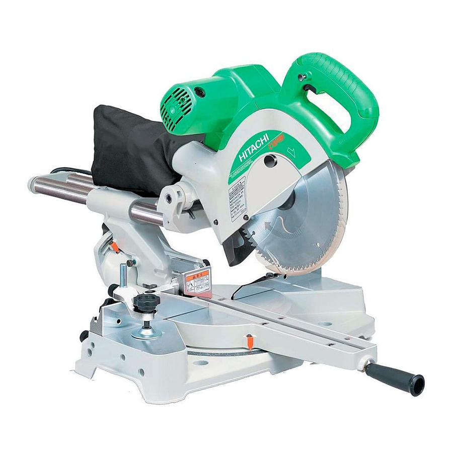
Slide Compound Miter Saw
Model C 10FSH
C 10FSB
Handling instructions
NOTE:
Before Using this Power Tool, carefully read through these
HANDLING INSTRUCTIONS to ensure efficient, safe operation. It is
recommended that these INSTRUCTIONS be kept readily available
as an important reference when using this power tool.
(Laser Marker Equipment)
Advertisement
Table of Contents

Related Manuals for Hitachi C 10FSH


Summary of Contents for Hitachi C 10FSH
-
Page 1: Handling Instructions
Slide Compound Miter Saw Model C 10FSH (Laser Marker Equipment) C 10FSB Handling instructions NOTE: Before using this Power Tool, carefully read through these HANDLING INSTRUCTIONS to ensure efficient, safe operation. It is recommended that these INSTRUCTIONS be kept readily available... - Page 2 GENERAL OPERATIONAL PRECAUTIONS WARNING! When using power tools basic safety precautions should always be followed to reduce the risk of fire, electric shock and personal injury, including the following. Read all these instructions before attempting to operate this product and save these instructions.
- Page 3 22. Warning The use of any accessory or attachment other than one recommended in this handling instructions or the HITACHI catalog may present a risk of personal injury. 23. Repairing must be done only by authorized service facility. Manufacturer is not responsible for any damages and injuries due to the repair by the unauthorized persons as well as the mishandling of the tool.
- Page 4 PRECAUTION ON USING SLIDE COMPOUND MITER SAW Review this Manual and familiarize yourself with the safety rules and operating instructions for this POWER TOOL before attempting to use it. Always confirm that the POWER TOOL is clean before using it. Always wear snug-fitting clothing, non-skid footwear (preferably with steel toes) and eye protection when operating the POWER TOOL.
-
Page 5: Name Of Parts
NAME OF PARTS Motor Lever (A) Head Gear Case Handle Dust Bag Spindle Cover Motor (Only Model 240V) Hinge Washer (D) Holder (A) Lower Guard Sub Cover Rotation Direction Indicator (For right bevel scale) Fence (A) Laser Marker (Only C10FSH) Indicator Saw Blade (For miter scale) -
Page 6: Specifications
SPECIFICATIONS Item Model C10FSH / C10FSB Motor Type Series commutator motor Power source Single-phase AC 50Hz Voltage (Volts) (230V, 240V) Power input 1450W Laser Marker Maximum output <1mW CLASS II Laser Product (Only Model Wave length 400~700 nm C10FSH) Laser medium Laser Diode Applicable Outside Dia. -
Page 7: Standard Accessories
4 Crown molding Vise Ass’y (Include Crown molding Stopper (L)) 5 Crown molding Stopper (L) 6 Crown molding Stopper (R) NOTE: Accessories are subject to change without any obligation on the part of the HITACHI. APPLICATIONS Wood and aluminum sash. -
Page 8: Preparation Before Operation
PREPARATION BEFORE OPERATION Make the following preparations before operating the power tool: 1. Installation Base 8mm (5/16") Bolt 150mm (5-29/32") (11/32") 3 Holes 300mm (11-13/16") Work Bench 8mm (5/16") Nut Fig. 4 Attach the power tool to a level, horizontal work bench in accordance with Fig. 4. Select 8mm (5/16") diameter bolts suitable in length for the thickness of the work bench. -
Page 9: Before Using
3. Installing the dust bag, holder, stopper and vises (The holder and stopper are optional accessories.) Attach the dust bag and vise assembly as indicated in Fig. 1 and Fig. 2. BEFORE USING 1. Make sure the power source is appropriate for the tool. WARNING: Never connect the power tool unless the available AC power source is of the same voltage as that specified on the nameplate of the tool. - Page 10 7. Check the lower limit position of the Saw Blade. Although it was adjusted before shipment, carefully check the height of the saw blade. Confirm that the saw blade can be lowered 10mm to 11mm (13/32" to 7/16") below the table insert.
-
Page 11: Before Cutting
BEFORE CUTTING 1. Cutting a groove on the guard Holder (A) has a guard (see Fig. 8) into which a Handle groove must be cut. Holder (A) Loosen the 6mm knob bolt to retract the guard Knob Bolt slightly. After placing a suitable wooden piece to Guard sit on the fence and the table surfaces, fix it with Vise... - Page 12 CAUTION: After adjusting the table insert for right angle cutting, the table insert will be cut to some extent if it is used for bevel angle cutting. When bevel cutting operation is required, adjust the table insert for bevel angle cutting. 3.
- Page 13 (2) Lower the motor head, and thrun the 8mm depth adjustment bolt by hand and make adjustments so that there can be a clearance of 2mm to 3mm (3/32" to 1/8") between the lower limit position of the motor head and the top of the workpiece at the saw blade's lower limit position (where the head of the 8mm depth adjustment bolt contacts the gear case.
- Page 14 7. Securing the workpiece WARNING: Always clamp or vise to secure the workpiece to the fence; otherwise the workpiece might be thrust from the table and cause bodily harm. 8. Installing the holders ... (Optional accessory) The holders help keep longer workpieces stable and in place during the cutting operation.
- Page 15 10. Confirmation for use of sub fence (A)…(Optional accessory) WARNING: In the case of right bevel cutting, remove the sub fence (A). Supposing it is not able to remove it, It will contact the blade or some part of the tool, causing in serious injury to operator.
- Page 16 12. Position adjustment of laser line (Only Model C10FSH) WARNING: * Make sure before plugging the power plug into the receptacle that the main body and the laser marker are turned off. * Exercise utmost caution in handling a switch trigger for the position adjustment of the laser line, as the power plug is plugged into the receptacle during operation.
- Page 17 Ink lining can be easily made on this tool to the laser marker. A switch lights up the laser marker. Switch (Fig. 20) Depending upon your cutting choice, the laser line can be aligned with the left side of the cutting width Laser line (saw blade) or the ink line on the right side.
-
Page 18: Practical Applications
NOTE: Check and make sure on a periodic basis if the position of the laser line is in order. As regards the checking method, draw a right-angle ink line on the workpiece with the height of about 20mm (25/32") and the width of 150mm (5-29/32"), and check that the laser line is in line with the ink line [The deviation between the ink line and the laser line should be less than the ink line width (0.5mm)]. - Page 19 Therefore, the vise assembly can be attached in either of three positions to ensure proper height adjustment. After adjusting the height, firmly tighten the 6mm wing bolt; then turn the upper knob, as necessary, to securely attach the workpiece in position. CAUTION: Always confirm that the motor head (see Fig.
- Page 20 * Every time one cutting or deep-cutting operation is finished, turn the switch off, and check that the saw blade has stopped. Then raise the handle, and return it to the full retract position. * Be absolutely sure to remove the cut material from the top of the turntable, and then proceed to the next step.
- Page 21 CAUTION: * When cutting a workpiece of 88mm (3-15/32") height, adjust the lower limit position of the motor head so that the gap between the lower edge of the motor head and the workpiece will be 2 to 3mm (3/32" to 1/8") at the lower limit position.
- Page 22 When stopping the bevel cutting operation halfway, start cutting after pulling back the motor head to the initial position. Starting from halfway, without pulling back, causes the lower guard to be caught in the cutting groove of the workpiece and to contact the saw blade.
- Page 23 CAUTION: Always secure the workpiece with the right or left hand and cut it by sliding the round portion of the saw backwards with the left hand. It is very dangerous to rotate the turntable to the left during compound cutting because the saw blade may come into contact with the hand that is securing the workpiece.
- Page 24 30° and 33.9° left slant setting method (1) Loosen the clamp lever and slant to the left a Fixing pin Holder (A) little at a time while pushing the fixing pin into the main unit. At this time, the fixing pin will enter one step and fit into the 30°...
- Page 25 Fence Fence Table on Base Table on Base Fig. 39 Fig. 40 (3) Setting to cut crown moldings at positions 1 and 4 in Fig. 35 (see Fig. 41; tilt the head to the right): 1 Turn the turntable to the right and set the Miter Angle as follows: * For 45°...
- Page 26 Cutting method of crown molding without tilting the saw blade. (1) Crown molding Stopper (L) and (R) (optional Crown molding accessories) allow easier cuts of crown Crown molding Stopper (R) Vise Ass’y molding without tilting the saw blade. Install (optional (optional them in the base both-sides side to be shown accessories)
- Page 27 CAUTION: Always confirm that the motor head (see Fig. 1) does not contact the crown molding vise ass’y when it is lowered for cutting. If there is any danger that it may do so, loosen the 6mm knob bolt and move the crown molding vise ass’y to a position where it will not contact the saw blade.
- Page 28 12. Cutting easily-deformed materials, such as aluminum sash Materials such as aluminum sash can easily deform when tightened too much in a vise assembly. This will cause inefficient cutting and possible overload of the motor. When cutting such materials, use a wood plate to protect the workpiece as shown in Fig.
-
Page 29: Saw Blade Mounting And Dismounting
SAW BLADE MOUNTING AND DISMOUNTING WARNING: * To prevent an accident or personal injury, always turn off the trigger switch and disconnect the power plug from the receptacle before removing or installing a saw blade. If cutting work is done in a state where the bolt is not sufficiently tightened, the bolt can get loose, the blade can come off, and the lower guard can get damaged, resulting in injuries. -
Page 30: Maintenance And Inspection
(4) Lift the lower guard and mount the saw blade. WARNING: When mounting the saw blade, confirm that the rotation indicator mark on the saw blade and the rotation direction of the gear case (see Fig. 1) are properly matched. (5) Thoroughly clean washer (D), collar and the bolt, and install them onto the saw blade spindle. - Page 31 Fig. 52 3. Inspecting the carbon brushes For your continued safety and electrical shock protection, carbon brush inspection and replacement on this tool should ONLY be performed by a Hitachi Authorized Service Center. 4. About Handling the Motor (see Fig. 1) Winding of the motor is said to be the heart of this tool.
- Page 32 12. Replacing supply cord If the supply cord of Tool is damaged, the Tool must be returned to Hitachi Authorized Service Center for the cord to be replaced.
-
Page 33: Service And Repairs
Repair, modification and inspection of Hitachi Power Tools must be carried out by a Hitachi Authorized Service Center. This Parts List will be helpful if presented with the tool to the Hitachi Authorized Service Center when requesting repair or other maintenance. - Page 34 C10FSH...
- Page 35 C10FSH...
- Page 36 C10FSH 142 143 153 154 155 156 157 158 159 160 223 224 143 145 146 231 224...
- Page 37 C10FSH 305-180 996-276 305-179 321-332 312-488 961-554 M8 × 10 329-409 302-518 ”80” 965-077 984-528 321-330 319-270 949-429 949-312 949-215 M4 × 8 949-633 M8 × 50 320-141 320-141 303-409 M8 × 25 312-672 321-370 ”14-20” 949-237 M5 × 12 308-396 949-454 M4 ×...
- Page 38 C10FSH 151 1 321-354 110V-120V 949-555 151 2 322-200 220V-240V 988-821 930-804 M4.0 307-732 321-380 –––––––– 301-653 D4 × 20 322-454 880-734 M5 × 25 312-492 319-503 322-884 ”160” 321-383 321-398 6201VVCMNS7S 959-141 976-819 980-063 322-456 322-884 ”218” 302-757 321-356 935-196 M4 ×...
- Page 39 C10FSB...
- Page 40 C10FSB...
- Page 41 C10FSB 133 134 135 208 201 122 123 129 130 131 132 200 201...
- Page 42 C10FSB 305-180 961-554 M8 × 10 305-179 302-518 ”79” 312-488 984-528 329-409 949-312 965-077 949-633 M8 × 50 321-330 320-141 949-429 949-237 M5 × 12 949-215 M4 × 8 949-454 M4 × 12 320-141 998-980 303-409 M8 × 25 322-199 321-370 ”14-20”...
- Page 43 C10FSB 149 2 340-779F 230V-240V ”148” 964-851 953-174 D5 × 55 304-043 M4 × 10 321-399 608VVC2NS7L 960-017 M6 × 32 152 1 360-898E 230V ”151, 196” 987-860 M6 × 6 152 2 360-898F 240V ”151, 196” 321-552 946-362 –––––––– 945-161 321-387 ”609-612”...
- Page 44 Hitachi Koki Co., Ltd. Code No. C99115015 F Printed in China...
Need help?
Do you have a question about the C 10FSH and is the answer not in the manual?
Questions and answers