
Related Manuals for Crestron FTI-PWR-D


Summary of Contents for Crestron FTI-PWR-D
- Page 1 Crestron FTI-PWR-D FlipTop Power Center - International Version Operations & Installation Guide...
- Page 2 Rockleigh, NJ 07647 1-888-CRESTRON Regulatory Compliance As of the date of manufacture, the FTI-PWR-D-B and FTI-PWR-D-BALUM have been tested and found to comply with specifications for CE marking and standards per EMC and Radiocommunications Compliance Labelling. Federal Communications Commission (FCC) Compliance Statement This device complies with part 15 of the FCC Rules.
-
Page 3: Table Of Contents
Crestron FTI-PWR-D FlipTop Power Center - International Version Contents FlipTop Power Center - International Version: FTI-PWR-D Introduction ..........................1 Features and Functions ....................1 Applications......................... 2 Specifications ......................2 Physical Description....................3 Setup ............................6 Installation ........................6 Hardware Hookup ..................... 11 Operation .......................... -
Page 5: Fliptop Power Center - International Version: Fti-Pwr-D
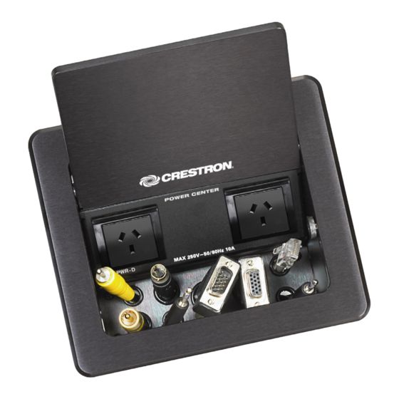
International Version: FTI-PWR-D Introduction The FTI-PWR-D provides an elegant connectivity solution in a stylish flush mount tabletop package. Beneath the "FlipTop" lid, the cable storage compartment keeps interface cables at the ready for plugging in computers, AV sources, and a host of other devices. -
Page 6: Applications
FlipTop Power Center – International Version Crestron FTI-PWR-D Applications The following diagram shows an FTI-PWR-D in a lecture hall application. FTI-PWR-D in a Lecture Hall Application Specifications Specifications for the FTI-PWR-D are listed in the following table. FTI-PWR-D Specifications SPECIFICATION... -
Page 7: Physical Description
FTI-PWR-D. FTI-PWR-D Physical View FTI-PWR-D Overall Dimensions (Top View) 216 mm (8.50 in 173 mm (6.83 in) 169 mm (6.67 in) FlipTop Power Center – International Version: FTI-PWR-D • 3 Operations & Installation Guide – DOC. 6797B... - Page 8 FTI-PWR-D Overall Dimensions (Rear View) FTI-PWR-D Overall Dimensions (Side View) 76 mm (2.98 in) 116 mm (4.57 in) 142 mm (5.58 in) 205 mm (8.09 in) 4 • FlipTop Power Center – International Version: FTI-PWR-D Operations & Installation Guide – DOC. 6797B...
- Page 9 Maximum Load: 10 Amps @ 250 Volts AC, 50/60 Hz MAX 250V~50/60Hz 10A (1) IEC socket Passes through to front panel AC power outlet FlipTop Power Center – International Version: FTI-PWR-D • 5 Operations & Installation Guide – DOC. 6797B...
-
Page 10: Setup
Screws, #04-40 x 1/4" (~7 mm) 2007158 The cable support plate should be installed before mounting the FTI-PWR-D to a surface. The cables are threaded through the cable support plate. 1. Place bushings on the cables you wish to install in the power center (eight bushings supplied). - Page 11 FlipTop Power Center - International Version Cable Support Plate Installation When selecting cables for installation in the FTI-PWR-D, cable connector length and strain relief diameter are important considerations. If the connector is too long, it can interfere with cover operation.
- Page 12 FlipTop box. Surface Mounting The FTI-PWR-D is designed to mount in a horizontal surface, such as a desk top, lectern, or podium. The following diagram illustrates the required opening size to accommodate the FTI-PWR-D. Use the template supplied with the FTI-PWR-D (4508463) to make the cutout.
- Page 13 (two screws per bracket). Refer to the illustration on the following page. 4. Slide the mounting brackets over the #06-32 screws and tighten the #06-32 screws. FlipTop Power Center – International Version: FTI-PWR-D • 9 Operations & Installation Guide – DOC. 6797B...
- Page 14 DO NOT OVER-TIGHTEN. CAUTION: Do not over-tighten the #10-32 screws as this may damage the surface and/or the unit. FTI-PWR-D (Mounting Brackets Installed) 10 • FlipTop Power Center – International Version: FTI-PWR-D Operations & Installation Guide – DOC. 6797B...
-
Page 15: Hardware Hookup
The ratings on the connecting unit's supply input should be considered to prevent overloading the wiring. FlipTop Power Center – International Version: FTI-PWR-D • 11 Operations & Installation Guide – DOC. 6797B... -
Page 16: Operation
AV, communication, data or control cables to be instantly available for connection to your devices. The recessed compartment also contains two grounded AC sockets. 12 • FlipTop Power Center – International Version: FTI-PWR-D Operations & Installation Guide – DOC. 6797B... -
Page 17: Problem Solving
Crestron's award winning customer service team by calling Crestron at 1-888-CRESTRON [1-888-273-7876]. You can also log onto the online help section of the Crestron website (www.crestron.com/onlinehelp) to ask questions about Crestron products. First-time users will need to establish a user account to fully benefit from all available features. -
Page 18: Appendix: International Power Receptacles
Algeria, Belgium, Cameroon, Central African Republic, Comoros, Congo POWER Democratic Republic, Djibouti, France, French Guiana, Gabon, RECEPTACLE, Guadeloupe, Guinea, Indonesia, Madagascar, Mali, Martinique, Togo FRANCE, 250V, 16A, BLK 14 • FlipTop Power Center – International Version: FTI-PWR-D Operations & Installation Guide – DOC. 6797B... -
Page 19: Return And Warranty Policies
Purchasers should inquire of the dealer regarding the nature and extent of the dealer's warranty, if any. CRESTRON shall not be liable to honor the terms of this warranty if the product has been used in any application other than that for which it was intended or if it has been subjected to misuse, accidental damage, modification or improper installation procedures. - Page 20 Crestron Electronics, Inc. Operations & Installation Guide – DOC. 6797B 15 Volvo Drive Rockleigh, NJ 07647 (2023946) Tel: 888.CRESTRON 06.10 Fax: 201.767.7576 Specifications subject to www.crestron.com change without notice.
Need help?
Do you have a question about the FTI-PWR-D and is the answer not in the manual?
Questions and answers