
Related Manuals for N-Tron 100-POE4


Summary of Contents for N-Tron 100-POE4
-
Page 1: User Manual
100-POE4 Unmanaged Industrial 4-Port Mid-Span POE PSE User Manual & Installation Guide (Revised 2011-09-02) - Page 2 Industrial 4-Port Mid-Span POE PSE Installation Guide 100-POE4 (Revised 2011-09-02)
- Page 3 In no event shall N-TRON Corp. be liable for any incidental, special, indirect or consequential damages whatsoever included but not limited to lost profits arising out of errors or omissions in this manual or the information contained herein.
-
Page 4: General Safety Warnings
Do not operate the equipment in the presence of flammable gasses or fumes. Operating electrical equipment in such an environment constitutes a definite safety hazard. WARNING: If the equipment is used in the manner not specified by N-TRON Corp., the protection provided by the equipment may be impaired. -
Page 5: Hazardous Location Installation Requirements
7. Class I, Div 2 installations require that all devices connected to this product must be UL listed for the area in which it is installed. 8. WARNING: Damage may occur to the RJ-45 port of the powered device (PD), if the 100-POE4 is not powered down before disconnecting the Cat5E cable. - Page 6 Functional Overview The 100-POE4 industrial 4-port Mid-Span POE PSE is designed to provide power over Ethernet for POE capable devices where running a power line is either not possible or not cost effective. This feature allows an end user to power a POE camera, wireless access point, or any other POE capable device without the need for running separate wires for power.
-
Page 7: Package Contents
PACKAGE CONTENTS Please make sure the package contains the following items: 100-POE4 Instruction Sheet Contact your carrier if any items are damaged. UNPACKING Remove all the equipment from the packaging, and store the packaging in a safe place. File any damage claims with the carrier. - Page 8 35mm DIN rail. However, DIN rail mounting may not be suitable for all applications. Our Universal Rack Mount Kit (P/N: URMK) may be used to mount the 100-POE4 enclosures to standard 19" racks as an option. (Revised 2011-09-02)
-
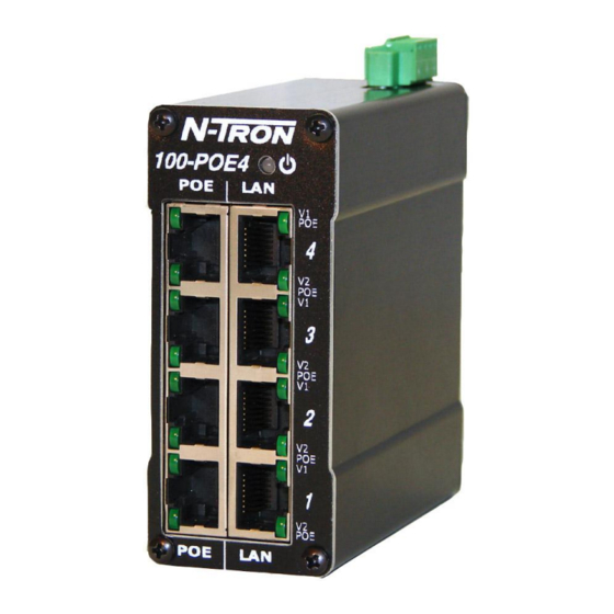
Page 9: Front Panel
FRONT PANEL From Top to Bottom: Power LED V1 POE POE is being applied on the respective port with V1 as a valid source of power. V2 POE is being applied on the respective port with V2 as a valid source of power. LEDs: The table below describes the operating modes (Port LEDs are for power supply status only and do NOT indicate link or activity): Note: Redundant power inputs will not balance the power load. - Page 10 DC Voltage sources. Use wire sizes of 20-10 gauge. The power cord should be limited to less than 10 meters in order to ensure optimum performance. Recommended 48V DC Power Supplies, similar to: 100-240VAC: N-Tron NTPS-48-5, DC 48V/5A or N-Tron NTPS-48-2, DC 48V/2A (Revised 2011-09-02)
- Page 11 (i.e. CE) are obtained when the N-Tron switch chassis is connected to earth ground via a drain wire. Some N-Tron switches have metal din-rail brackets that can ground the switch if the din-rail is grounded. In some cases, N-Tron switches with metal brackets can be supplied with optional plastic brackets if isolation is required.
-
Page 12: Rj45 Connector Crimp Specifications
RJ45 CONNECTOR CRIMP SPECIFICATIONS Please reference the illustration below for your Cat5 cable specifications: (Revised 2011-09-02) -
Page 13: Typical Application
1. Make sure the (Power LED) is ON. 2. Make sure you are supplying sufficient current for the 100-POE4 and all the powered devices plugged into it. Note: The inrush current and steady state current is dependent on the power requirements of the powered devices plugged into the 100-POE4. -
Page 14: Fcc Statement
FCC STATEMENT This product complies with Part 15 of the FCC-A Rules. Operation is subject to the following conditions: (1) This device may not cause harmful interference (2) This device must accept any interference received, including interference that may cause undesired operation. - Page 15 Regulatory Approvals: Safety: UL Listed per ANSI/ISA-12.12.01-2000 (US and Canada) and is listed for use in Class I, Div 2, Groups A, B, C, D, T4A EMI: EN 61000-6-4, EN 55011 - Class A FCC Title 47, Part 15, Subpart B - Class A ICES-003 –...
-
Page 16: Key Specifications
KEY SPECIFICATIONS Physical Height: 3.5” (8.89cm) Width: 1.489” (3.78cm) Depth: 3.53” (8.96cm) Weight: 0.7 lbs. (0.31kg) DIN-Rail: 35mm Electrical Input Voltage: 46-49 VDC Steady Input Current: 1.6 A @ 48 VDC (under full load) Steady Input Current: 30 mA @ 48 VDC (under no load) Inrush Current: 27 Amp/1.5 ms @ 48VDC (under full load) 24 Amp/1.5 ms @ 48VDC (under no load) - Page 17 Responsibility for loss or damage does not transfer to N-TRON until the returned item is received by N-TRON. The repaired or replaced item will be shipped to the customer, at N-TRON’s expense, not later than thirty (30) days after N-TRON receives the product.
Need help?
Do you have a question about the 100-POE4 and is the answer not in the manual?
Questions and answers