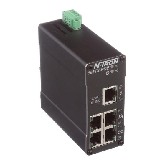
Summary of Contents for N-Tron 105FX-POE
- Page 1 105TX-POE & 105FX-POE Unmanaged Industrial Ethernet POE Switches User Manual & Installation Guide Rev. 041008...
- Page 2 Industrial Power over Ethernet Installation Guide 105TX-POE 105FX-XX-POE 105FXE-XX-YY-POE Where: XX = ST or SC and YY = -15, -40, or -80 Rev. 041008...
- Page 3 In no event shall N-TRON Corp. be liable for any incidental, special, indirect or consequential damages whatsoever included but not limited to lost profits arising out of errors or omissions in this manual or the information contained herein.
-
Page 4: General Safety Warnings
Do not operate the equipment in the presence of flammable gasses or fumes. Operating electrical equipment in such an environment constitutes a definite safety hazard. WARNING: If the equipment is used in the manner not specified by N-TRON Corp., the protection provided by the equipment may be impaired. -
Page 5: Hazardous Location Installation Requirements
7. Class I, Div 2 installations require that all devices connected to this product must be UL listed for the area in which it is installed. 8. WARNING: Damage may occur to the RJ-45 port of the powered device (PD), if the switch is not powered down before disconnecting the Cat5 cable. - Page 6 POE capable device without the need for running separate wires for power. This also allows the ability for a centralized battery backup for all these devices. The 105FX-POE utilizes the IEEE compliant SC or ST duplex connectors for fiber optic communication. All 10/100Base-TX ports utilize the RJ45 shielded connectors.
-
Page 7: Package Contents
PACKAGE CONTENTS Please make sure the switch package contains the following items: 105TX-POE or 105FX(E)-POE Instruction Sheet Contact your carrier if any items are damaged. UNPACKING Remove all the equipment from the packaging, and store the packaging in a safe place. File any damage claims with the carrier. - Page 8 DIN rail. Rotate the bottom of the unit towards you and up at an approximate 15° upward angle to completely remove the unit. Most N-Tron™ designed to be mounted on industry standard 35mm DIN rail. However, DIN rail mounting may not be suitable for all applications.
-
Page 9: Front Panel
FRONT PANEL From Top to Bottom: Power LED POE Status LED Speed LED (105TX-POE only) LNK/ACT Link/Activity LED RJ45 Ports Auto sensing 10/100BaseT Connection LED MODE OF OPERATION Note: Redundant power inputs will not balance the power load. Only load from one power supply is used at a time. - Page 10 DC Voltage sources. Use wire sizes of 10-20 gauge. The power cord should be limited to less than 10 meters in order to ensure optimum performance. Recommended 48V DC Power Supplies, similar to: 100-240VAC: N-Tron NTPS-48-5, DC 48V/5A Rev. 041008...
- Page 11 (i.e. CE) are obtained when the N-Tron switch chassis is connected to earth ground via a drain wire. Some N-Tron switches have metal din-rail brackets that can ground the switch if the din-rail is grounded. In some cases, N-Tron switches with metal brackets can be supplied with optional plastic brackets if isolation is required.
-
Page 12: Rj45 Connector Crimp Specifications
RJ45 CONNECTOR CRIMP SPECIFICATIONS Please reference the illustration below for your Cat5 cable specifications: Rev. 041008... -
Page 13: Typical Applications
TYPICAL APPLICATIONS STAR TOPOLOGY Rev. 041008... -
Page 14: Ring Topology
RING TOPOLOGY Rev. 041008... -
Page 15: Connecting The Unit
CONNECTING THE UNIT For the 100BaseFX Fiber Optic port (105FX-POE), remove the dust cap(s) from the fiber optic connector and connect the fiber optic cables. The TX port on the local unit should be connected to the RX port of the far end device, and the RX port should be connected to the TX port of the far end device. -
Page 16: Fcc Statement
FCC STATEMENT This product complies with Part 15 of the FCC-A Rules. Operation is subject to the following conditions: (1) This device may not cause harmful interference (2) This device must accept any interference received, including interference that may cause undesired operation. - Page 17 Regulatory Approvals: Safety: UL Listed per ANSI/ISA-12.12.01-2000 (US and Canada) This apparatus is suitable for use in Class I, Div 2, Groups A, B, C, D, T4 EMI: EN 61000-6-4, EN 55011 - Class A FCC Title 47, Part 15, Subpart B - Class A ICES-003 –...
-
Page 18: Key Specifications
4.22” (10.72 cm) 0.70 lbs. (0.32 kg) 46-49 VDC 1.6 A @ 48 VDC (under full load) 65 mA @ 48 VDC (no POE in use, switch in full use) 26 Amp/1.3 ms @ 48VDC Less than 100 mV 10-20 AWG -40°C to 85°C... - Page 19 Responsibility for loss or damage does not transfer to N-TRON until the returned item is received by N-TRON. The repaired or replaced item will be shipped to the customer, at N-TRON’s expense, not later than thirty (30) days after N-TRON receives the product.


Need help?
Do you have a question about the 105FX-POE and is the answer not in the manual?
Questions and answers