
Subscribe to Our Youtube Channel
Related Manuals for N-Tron 100-POE-SPL


Summary of Contents for N-Tron 100-POE-SPL
-
Page 1: User Manual
100-POE-SPL Industrial Power Extractor User Manual & Installation Guide (Revised 2010-11-15) - Page 2 Industrial PoE Power Extractor Installation Guide 100-POE-SPL-XX Unmanaged Industrial PoE Power Extractor Where "XX" is: 12 for 12VDC output voltage option 24 for 24VDC output voltage option 48 for 48VDC output voltage option XX custom output voltages <24VDC upon request...
- Page 3 In no event shall N-TRON Corp. be liable for any incidental, special, indirect or consequential damages whatsoever included but not limited to lost profits arising out of errors or omissions in this manual or the information contained herein.
-
Page 4: Electrical Safety Warnings
Do not operate the equipment in the presence of flammable gasses or fumes. Operating electrical equipment in such an environment constitutes a definite safety hazard. WARNING: If the equipment is used in the manner not specified by N-TRON Corp., the protection provided by the equipment may be impaired. - Page 5 WARNING: Disconnect the power and allow to cool 5 minutes before touching. 100-POE-SPL-XX Industrial Power Extractor The 100-POE-SPL-XX is a PoE splitter designed to accept Ethernet with PoE via Cat5e cable and output power via terminal block and Ethernet via RJ-45. This allows devices which are not PoE capable to be connected and powered by a Cat5e cable connected to a PoE sourcing device.
-
Page 6: Package Contents
PACKAGE CONTENTS Please make sure the package contains the following items: 100-POE-SPL-XX PoE Power Extractor Product CD Contact your carrier if any items are damaged. UNPACKING Remove all the equipment from the packaging, and store the packaging in a safe place. File any damage claims with the carrier. - Page 7 URMK 1000-PM Most N-Tron™ products are designed to be mounted on industry standard 35mm DIN rail. However, DIN rail mounting may not be suitable for all applications. Our Universal Rack Mount Kit (P/N: URMK) may be used to mount the 100-POE-SPL-XX enclosures to standard 19" racks, and our Panel Mount Assembly (P/N: 1000-PM) may be used to mount the 100-POE-SPL-XX enclosures to a panel or any other flat surface.
-
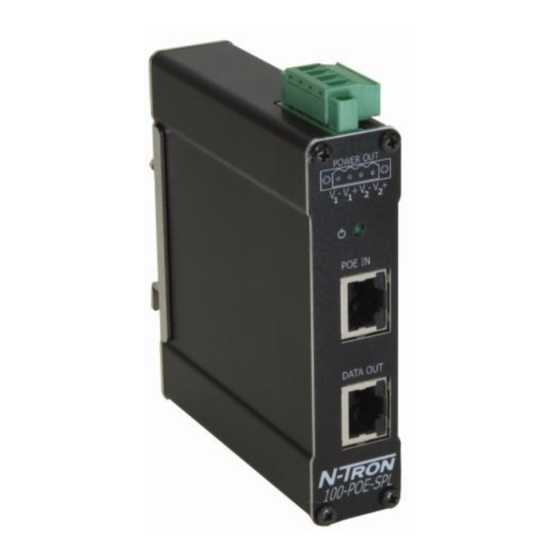
Page 8: Front Panel
FRONT PANEL From Top to Bottom: Green Terminal Block Voltage output 12/24/48VDC connector (Model dependent) Green LED lights when Power is present POE IN RJ45 connector for data and PoE in DATA OUT RJ45 connector for data only out LEDs: The table below describes the operating modes: Color Description Power is Applied... - Page 9 Recommended PoE Power Source Equipment, similar to: N-Tron 105TX-POE, 4 End Span PoE Ports (48VDC on Data Pair) N-Tron 105FX-POE, 4 End Span PoE Ports (48VDC on Data Pair) N-Tron 100-POE4, 4Mid Span PoE Ports (48VDC on Spare Pairs)
- Page 10 (i.e. CE) are obtained when the N-Tron switch chassis is connected to earth ground via a drain wire. Some N-Tron switches have metal din-rail brackets that can ground the switch if the din-rail is grounded. In some cases, N-Tron switches with metal brackets can be supplied with optional plastic brackets if isolation is required.
-
Page 11: Connecting The Unit
100-POE-SPL-XX and the POE Extractor will convert that voltage to 12/24/48VDC for the legacy end device. Warning: The 100-POE-SPL-XX is not a switch and will not actively boost the Ethernet signals. So the total max segment length is a combined 100meters. Meaning the length of the cable on the DATA OUT port plus the length of the cable on the POE IN port may not exceed 100meters in total. -
Page 12: Fcc Statement
FCC STATEMENT This product complies with Part 15 of the FCC Rules. Operation is subject to the following conditions: (1) This device may not cause harmful interference, and (2) This device must accept any interference received, including interference that may cause undesired operation. - Page 13 100-POE-SPL-XX - KEY SPECIFICATIONS Physical 4.30” (10.92 cm) Height: 1.00” (2.54 cm) Width: 3.91” (9.94 cm) Depth w/ typical SFP installed: 4.15” (10.55 cm) Including Din-Rail Mount: Weight: 0.60 lbs (0.27 kg) DIN Rail: 35 mm Electrical Input Voltage: PoE 48VDC (IEEE 802.3af) Input Current: 10mA max.
- Page 14 Regulatory Approvals: Safety: UL Listed per UL 508 and ISA-12.12.01-2007 (US and Canada) for use in Class I, Div 2, Groups A, B, C, D, hazardous or non-hazardous locations; temperature code of T4. EMI: EN61000-6-4, EN55022 - Class A FCC Title 47, Part 15, Subpart B - Class A ICES-003 –...
- Page 15 Responsibility for loss or damage does not transfer to N-TRON until the returned item is received by N-TRON. The repaired or replaced item will be shipped to the customer, at N-TRON’s expense, not later than thirty (30) days after N-TRON receives the product.
Need help?
Do you have a question about the 100-POE-SPL and is the answer not in the manual?
Questions and answers