
Subscribe to Our Youtube Channel
Related Manuals for N-Tron 7506GX2


Summary of Contents for N-Tron 7506GX2
-
Page 1: User Manual
7506GX2 Managed Industrial Gigabit Ethernet Switch User Manual & Installation Guide Page 1 of 158 (Revised 2011-07-21) -
Page 2: Table Of Contents
7506GX2 Managed Industrial Gigabit Ethernet Switch Installation Guide ..............4 7506GX2 Industrial Ethernet Switch Accessories ....................... 6 SAFETY WARNINGS ..............................8 Installation ..................................9 Connecting the Unit ..............................14 Overview of Advanced Features ..........................18 Mode of Operation .................................. 18 Port Mirroring .................................. - Page 3 Example 4 – Basic understanding of Hybrid VLANs ......................153 Example 5 – Basic understanding of Overlapping VLANs....................154 Example 6 – Basic understanding of VLANs with Multicast Filtering ................. 155 KEY SPECIFICATION ............................156 N-TRON Limited Warranty ............................. 158 Page 3 of 158 (Revised 2011-07-21)
-
Page 4: 7506Gx2 Managed Industrial Gigabit Ethernet Switch Installation Guide
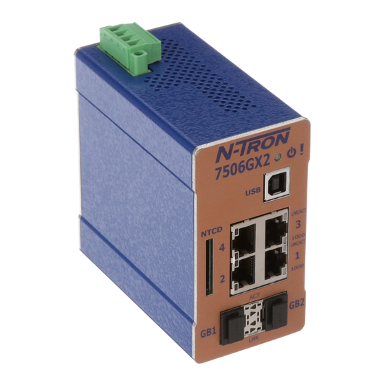
7506GX2 Managed Industrial Gigabit Ethernet Switch Installation Guide The N-TRON 7506GX2 Series Industrial Gigabit Ethernet Switch offers outstanding performance and ease of use. It is ideally suited for connecting Ethernet enabled industrial and or security equipment and is a fully managed switch. - Page 5 • 802.1Q tag VLAN and Port VLAN • 802.1p QoS, Port QoS, and DSCP • LLDP (Link Layer Discovery Protocol) • Trunk with other N-Tron trunking capable switches over two ports • Port Mirroring • 802.1d, 802.1w, 802.1D RSTP (Rapid Spanning Tree Protocol) •...
-
Page 6: 7506Gx2 Industrial Ethernet Switch Accessories
7506GX2 Industrial Ethernet Switch Accessories Configuration Device Ideal for saving, or restoring switch configuration parameters quickly without the need for a computer or software. One configuration device per switch is recommended. NTCD-SD Page 6 of 158 (Revised 2011-07-21) - Page 7 In no event shall N-Tron Corp. be liable for any incidental, special, indirect or consequential damages whatsoever included but not limited to lost profits arising out of errors or omissions in this manual or the information contained herein.
-
Page 8: Safety Warnings
SAFETY WARNINGS GENERAL SAFETY WARNINGS WARNING: If the equipment is used in the manner not specified by N-Tron Corp., the protection provided by the equipment may be impaired. Maximum surrounding air temperature rating: 80°C LASER SAFETY (7506GX2 Model with optional NTSFP-LX -10, -40 and -80) CAUTION: CLASS 1 LASER PRODUCT. -
Page 9: Installation
The SD Card connector is for temporary connection only. Do not use, connect, or disconnect unless area is known to be non-hazardous. Connection or disconnection in an explosive atmosphere could result in an explosion. Please make sure the 7506GX2 Ethernet Switch package contains the following items: 1. 7506GX2 Switch 2. Product CD Contact your carrier if any items are damaged. - Page 10 Remove all the equipment from the packaging, and store the packaging in a safe place. File any damage claims with the carrier. CLEANING Clean only with a damp cloth. Page 10 of 158 (Revised 2011-07-21)
- Page 11 DIN RAIL MOUNTING Install the unit on a standard 35mm Din-Rail. Recess the 7506GX2 unit to allow at least 3‖ of horizontal clearance for copper cable bend radius. Recess the 7506GX2 unit to allow at least 5‖ of horizontal clearance for fiber cable bend radius. There should be at least 3‖ of clearance on both the top and bottom of the unit to allow proper ventilation.
- Page 12 Command Line Interface (CLI) RJ45 Ports Auto Sensing 10/100/1000 Base-T Connections NTCD N-Tron Configuration Device Gigabit Ports 1000 Base SFP Fiber Transceivers (Optional) NOTE: The RJ45 data ports have two LEDs located on each connector. The bottom LED indicates the SPEED, and the top LED indicates LINK/ACTIVITY.
- Page 13 DC Voltage sources. This device will draw current from both sources simultaneously. Use 16-28 gauge wire when connecting to the power supply. Recommended 24V DC Power Supplies, similar to: N-Tron‘s P/N NTPS-24-1.3: Input AC 115/230V Power 30W ...
-
Page 14: Connecting The Unit
5E straight through or crossover cable with a minimum length of one meter and a maximum length of 100 meters. N-Tron recommends the use of pre- manufactured Cat5E cables to ensure the best performance. If this is not an option and users must terminate their own ends on the Cat5E cables;... - Page 15 Some N-Tron switches have metal din-rail brackets that can ground the switch if the din-rail is grounded. In some cases, N-Tron switches with metal brackets can be supplied with optional plastic brackets if isolation is required.
- Page 16 RJ45 CONNECTOR CRIMP SPECIFICATIONS Please reference the illustration below for your Cat5 cable specifications: Page 16 of 158 (Revised 2011-07-21)
- Page 17 Connect the USB port of your PC and the 7506GX2 Series Switch using a standard USB cable. You will require a cable with a Type A connector for the PC end, and a Type B connector for the 7506GX2 Series end.
-
Page 18: Overview Of Advanced Features
Overview of Advanced Features Mode of Operation Each port on the switch can be configured into different modes of operation as shown below: Copper Ports: 1000Base Fiber Ports: - Half Duplex - Full Duplex - Full Duplex - Auto Negotiation Half Duplex In half duplex mode, the CSMA/CD media access method is the means by which two or more stations share a common transmission medium. -
Page 19: Virtual Lan
VID or PVID defines a VLAN group with a membership of ports. This membership determines whether a port is included or excluded as to frame egress from the switch. The 7506GX2 Series switch also has the ability to allow overlapping VLANs. Overlapping VLANs give Page 19 of 158... -
Page 20: Rapid Spanning Tree Protocol
STP when desired. SNMP Traps The 7506GX2 switch supports up to 5 SNMP Trap Stations to which SNMP Traps will be sent. The switch supports five standard traps; Link Up, Link Down, Cold Start, Warm Start and Authentication Errors. -
Page 21: N-Ring
DHCP is controlled by RFC 2131. The N-Tron DHCP Switch can be configured to be a DHCP Client. Alternately the N-Tron DHCP switch can be configured to be a DHCP Server, a DHCP Relay Agent, or both. -
Page 22: Dhcp Client
DHCP Client The switch will automatically obtain an IP assignment from a DHCP Server, or optionally Fallback to a configured IP assignment if unable to get an IP assignment from a DHCP server. Communication between the client and server can optionally go through a DHCP Relay Agent. DHCP Relay Agent DHCP Relay Agent (Option 82) allows communication between the client and server to cross subnet and VLAN boundaries. - Page 23 ~ 2X. Verify that Link LEDs are ON for connected ports. Verify cabling used between stations. Verify that cabling is Category 5E or greater for 100/1000Mbit operation. SUPPORT Contact N-Tron Corp. at: TEL: 251-342-2164 FAX: 251-342-6353 E-MAIL: N-TRON_Support@n-tron.com WEB: www.n-tron.com...
-
Page 24: Web Software Configuration
Web Software Configuration Web Management Enter the switch‘s IP address in any web browser and login to the web management feature of the N-Tron switch. Default: User Name: admin Password: admin Page 24 of 158 (Revised 2011-07-21) -
Page 25: Web Management - Home
Web Management - Home When the administrator first logs onto an N-Tron Fully Managed switch the default home page will be displayed. On the left hand side of the screen there is a list of configurable settings that the switch will support. - Page 26 Web Management – Menu Structure To the left, there is a menu which is shown fully opened below. The pages opened by each of the individual selections are described in the rest of this section. The use of each of these pages is also described in this section.
-
Page 27: Administration - System
Administration – System The System tab under the Administration category, lists various information about the switch: When the IP Configuration is in either DHCP or Static Mode: IP Configuration Method used to obtain an IP Address, Subnet Mask and Gateway Address IP Address Contains the current IP Address of the device. - Page 28 Page 28 of 158 (Revised 2011-07-21)
- Page 29 Administration – System, Continued… When the IP Configuration is in DHCP Mode the following information is added: Client ID Option used by DHCP clients to specify their unique identifier. The identifier may be the MAC address, switch name, or entered as a text string or hex characters. Fallback IP Address Contains the configured Fallback IP Address of the device.
- Page 30 Administration – System, Continued… By selecting the Modify button, you will be able to change the switch‘s IP Configuration, Client ID, IP Address, Subnet Mask, Gateway, Name, Contact information, and the Location of the switch through the web management features, depending on the IP Configuration. It is recommended to change the TCP/IP information through the Command Line Interface (CLI) initially, but it defaults to the following: –...
- Page 31 Administration – System, Continued… If the IP Configuration mode is set to DHCP and the Fallback IP address is changed from the default IP address, then the switch will use the Fallback addresses if the IP configuration isn‘t received from a DHCP server in 2 minutes after initial boot.
-
Page 32: Administration - Snmp
Administration – SNMP The SNMP tab under the Administration category shows a list of IP Addresses that act as SNMP Traps. The Read-Only, Read-Write, and Trap Community Names are also shown here. By selecting the Modify button, you will be able to change any of the fields listed. This allows the user to set an IP address for a Trap station or change the Community Names. - Page 33 Administration – SNMP, Continued… Page 33 of 158 (Revised 2011-07-21)
-
Page 34: Administration - Fault
Administration – Fault The Fault tab under the Administration category provides configurable selections indicating the way to notify when a Power, N-Link or N-Ring Signal fault occurs. Power signal faults consist of V and V Link Faults can also be set for notification. The Power and N-Link notifications may consist of any combination of the options: Show Web and Show LED. -
Page 35: Dhcp - Server - Setup Profiles
DHCP – Server – Setup Profiles The Setup Profiles tab under the DHCP/Server category lists the following information about the current state of the server and the existing network profiles: Server Enabled Indicates whether the DHCP server is active. Allow Broadcast Indicates whether the DHCP server will process broadcast messages. - Page 36 DHCP – Server – Setup Profiles, Continued… Page 36 of 158 (Revised 2011-07-21)
-
Page 37: Dhcp - Server - Setup Ip Maps
There are two different data entry formats available according to whether the relay agent type is for an N-TRON or for a generic switch. To create a range of static IP addresses on an N-Tron relay agent switch: Network Profile An existing network profile to which the IP map applies. - Page 38 Should be set to N-TRON. Switch Model List of N-TRON models that support this feature. Remote ID A unique identifier that designates the N-TRON relay agent switch. Checkbox used to add an IP map for the corresponding port. Port No The actual port number.
- Page 39 DHCP – Server – Setup IP Maps, Continued… Page 39 of 158 (Revised 2011-07-21)
- Page 40 DHCP – Server – Setup IP Maps, Continued… To create a range of static IP addresses on a generic relay agent switch: Network Profile An existing network profile to which the IP map applies. Relay Agent Type Should be set to Generic. Port Count The number of ports on the particular relay agent switch.
- Page 41 DHCP – Server – Setup IP Maps, Continued… The Single IP type of mapping is used to create a static IP address for an individual client. The following information is required: Network Profile An existing network profile to which the IP map applies. The static IP address to offer to a client.
-
Page 42: Dhcp - Server - View Bindings
DHCP – Server – View Bindings The View Bindings tab lists the bindings of physical devices to IP addresses that are in use or offered: Network Profile The profile applied to the binding entry. Binding Identifier The client associated with the binding entry. Client Hardware Address (MAC) The client‘s MAC address. -
Page 43: Dhcp - Relay & Local Ip - Setup
DHCP – Relay & Local IP - Setup The Setup tab under the DHCP/Relay & Local IP category shows the current state of the relay agent. By selecting the Modify button, you can configure general settings of the relay agent, as well as, configure settings on a per port basis. - Page 44 DHCP – Relay & Local IP – Setup, Continued… Relay Status Indicates whether the DHCP relay agent is active. Remote ID The unique identifier that designates the relay agent switch. Server # IP The configured IP address of the DHCP servers. Port No The actual port number.
- Page 45 DHCP – Relay & Local IP – Setup, Continued… Page 45 of 158 (Revised 2011-07-21)
-
Page 46: Lldp - Configuration
LLDP - Configuration Mode: Enables or Disables LLDP on the Switch. Default: Disabled Transmit Interval: Specifies the interval at which LLDP frames are transmitted. Default = 30 seconds. Transmit Hold Multiplier: Specifies a multiplier on the Transmit Interval when calculating a Time-to-Live value. Default = 4. Re-Initialization Delay: Specifies the minimum time an LLDP port will wait before re-initializing after its setting has changed from disabled to Tx-Only or Tx/Rx. -
Page 47: Lldp - Ports
LLDP - Ports LLDP Ports View Port Name Descriptive name of the port on the local switch. Transmit Enables or Disables LLDP Transmission on the switch. Receive Enables or Disables Receiving of LLDP Frames from neighbor switches. Allow Management Data Allow the Transmission of Management type information. -
Page 48: Lldp - Status
LLDP - Status LLDP Ports Neighbor View The Status View shows the results of LLDP discovery. The LLDP Ethernet frames received from neighboring ports are composed of a collection of data units called TLVs. Each TLV contains a defined type of information such as the Chassis ID described below, which contains the MAC address of the device sending the frame. -
Page 49: Lldp - Statistics
LLDP - Statistics LLDP Local Port Statistics View Port Name Descriptive name of the port on the local switch. Transmitted Frames The total number of LLDP Frames sent out from the local switch. Received Frames Total number of LLDP frames received by the local switch. Discarded Frames The total number of frames discarded due to incorrect TLV's in frame. -
Page 50: Ports - Configuration
Ports – Configuration The Configuration tab under the Ports category will show a detailed overview of all the active ports on the switch. The overview will display the following information: Port Number This is the port index. Port Name This field displays the name of the port. The designation of TX is for copper ports, FX is for fiber optic ports, and GB is for the Gigabit ports (fiber or copper). - Page 51 Ports – Configuration, Continued… The User can click on the Port Number to configure each port individually. This will allow the user to change the port‘s settings for the following fields which are explained above: Admin Status Speed and Duplex Flow Control Force High Priority Default Priority...
-
Page 52: Ports - Mac Security - Learning
Ports – MAC Security – Learning The Learning tab allows the administrator to control the learning or locking modes for the ports. ‗Locked‘ is the secure mode. ‗Learning‘ builds an internal list of authorized MAC addresses based on an approved LAN. -
Page 53: Ports - Mac Security - Authorization List
Ports – MAC Security – Authorization List The Authorization List tab allows for manual entry or deletion of authorized MAC source addresses with associated authorized ports. Selecting Modify displays the MAC Authorization Configuration page, which allows the administrator to add new entries, delete existing entries, or edit authorized ports of existing entries. Selecting Delete removes the associated entry. -
Page 54: Ports - Mac Security - Intruder Log
Ports – MAC Security – Intruder Log The Intruder Log tab displays a list of unauthorized MAC addresses that attempted to access the secured device. Each intruder entry in the log is unique, and is based on the combination of MAC address, VLAN, and port. -
Page 55: Ports - Mirroring
Ports – Mirroring A mirroring port is a dedicated port that is configured to receive the copies of Ethernet frames that are being transmitted out and also being received in from any other port that is being monitored. The Mirroring tab under the Ports category displays the status including the list of Source Ports and the Destination Port that the Sources are being mirrored to. - Page 56 Ports – Mirroring, Continued… Following the Modify button, you can enable the status of port mirroring and select source ports and the destination port that the source ports will be mirrored to. Page 56 of 158 (Revised 2011-07-21)
-
Page 57: Ports - Trunking
Ports – Trunking The Trunking tab under the Ports category displays the following details: Trunk Ports This field displays the ports associated with the trunk. Trunk Status This configurable field displays the existing status of the trunk. It can be either Enabled/Disabled. By selecting the Modify button, you can select a trunk group. -
Page 58: Ports - Qos
Ports – QoS The QOS decision tree chooses the highest priority Transmit Queue (TQ) of the following criteria: 1. Force High Priority (Port Based) TQ mapping, 2. IEEE802.1p TQ mapping, or 3. DSCP (RFC 2474) TQ mapping. Each of these three methods is included or not based on the settings on this browser page. When Force High Priority is enabled, the port based priority is included in the TQ decision for all ports and all frames received on a port will use the default QOS priority for that port in the TQ decision. - Page 59 Page 59 of 158 (Revised 2011-07-21)
-
Page 60: Statistics - Port Statistics
Statistics – Port Statistics The Ports Statistics tab under the Statistics category displays a list of MIB parameters. Each port has a separate counter for each parameter. This gives users the ability to see what kind of packets are going over which ports. -
Page 61: Statistics - Port Utilization
The Ports Utilization tab under the Statistics category shows all the ports on the switch and will display a bar graph showing the percentage of bandwidth being used. These figures and bars are for a general feeling of what the bandwidth usage is. N-Tron recommends the use of N-View in order to get a precise bandwidth usage figure. -
Page 62: Vlan - Configuration
VLAN – Configuration Replace VID Tag with Default Port VID Specifies whether or not to replace the incoming VID tag with the port's designated VID. Perform Ingress Filtering Specifies whether or not to filter out ingress frames when a VID violation is detected. Discard Non-Tagged for Ports Specifies whether or not non-tagged ingress frames are dropped by the selected ports. - Page 63 VLAN – Group Configuration VLAN ID This field displays the VLAN ID. The range should be 1-4094. VLAN Name This configurable field displays the name of the VLAN, which accepts alphanumeric and special characters (#, _, -, .) only. Allow Management Specifies whether or not all ports in this VLAN are management ports.
-
Page 64: Bridging - Aging Time
Bridging – Aging Time The Aging Time tab under the Bridging category will display the currently configured Aging Time. This page allows users to modify this variable to meet their needs. After selecting the Modify button, the user will be presented with a page that allows the number to be entered and updated. -
Page 65: Bridging - Unicast Addresses
Bridging – Unicast Addresses The Unicast Addresses tab under the Bridging category will display a list of MAC addresses that are associated with each respective port number. This can be used to statically assign a MAC address access to a single port on the switch. Following the Add button on the page above, the administrator must enter a valid MAC address and associate it with a port number on the switch. - Page 66 Bridging – Unicast Addresses, Continued… Once a static MAC address has been added, it will be displayed in a list on the main page under Unicast MACs tab. Following the Remove button on the example above, an administrator can select a static MAC address from the list using a pull-down menu.
-
Page 67: Bridging - Multicast Addresses
Note: If there are multiple ports on different VLANs, the N-Tron switch will apply the static multicast address to the lowest VLAN-ID that is associated with one of the ports assigned to the static multicast address. - Page 68 Then click on the Remove button at the bottom of the page. Note: If there are multiple ports on different VLANs, the N-Tron switch will apply the static multicast address to the lowest VLAN-ID that is associated with one of the ports assigned to the static multicast address.
-
Page 69: Bridging - Show Mac By Port
Bridging – Show MAC by Port This feature shows the MAC addresses of devices connected to each switch port and the IP Addresses associated with the MACs. The browser page ‗View MAC by Port‘ shows the MAC for the device found on each port, and the IP for the MAC presented if available. - Page 70 When an IP has been manually entered a button is provided to ‗Delete IP‘, and invoking it will allow the administrator to delete the manual association of an IP to that MAC. Page 70 of 158 (Revised 2011-07-21)
-
Page 71: Rstp - Configuration
RSTP – Configuration The Configuration tab under the RSTP category will display the RSTP information for the first VLAN. Using the pull-down menu at the top of the page an administrator can choose which VLAN to configure RSTP on. Once the VLAN is selected, the administrator may configure the bridge by clicking on the ‗Configuration‘... - Page 72 RSTP – Configuration Continued… The configuration screen for the VLAN that was previously selected will look like the example below. Here the administrator can make changes such as the Hello Time, Forward Delay, Max Age, Priority, and the Status of RSTP on that VLAN. The administrator or user can see the current RSTP status of the ports on that VLAN by clicking on the ‗here‘...
- Page 73 RSTP – Configuration Continued… Following the link for the view RSTP Port Configuration at VLAN#, the administrator or user can see the current RSTP status of the ports on that VLAN. This will show information such as the Path Cost and the Port State.
- Page 74 RSTP – Configuration Continued… If the administrator selects one of the ports on the previous screen, he or she can change the Port‘s Path Cost, Priority, and the status of Admin Edge and Auto Edge. Page 74 of 158 (Revised 2011-07-21)
-
Page 75: Igmp - Configuration
IGMP – Configuration The Configuration tab under the IGMP category will display the IGMP basic configuration settings. By default, IGMP is enabled. Following the Modify button, the administrator will see a list of configurable fields for the IGMP configuration. Once these fields are filled in to meet the needs of the administrator‘s network, the changes may be updated by clicking the Update button at the bottom of the page. - Page 76 IGMP – Configuration, Continued… The IGMP Status pull-down allows the user to enable or disable IGMP completely. The Query Mode pull-down allows the user to set query mode for Automatic (the default), On (always), or Off (never): Page 76 of 158 (Revised 2011-07-21)
- Page 77 IGMP – Configuration, Continued… The Router Mode pull-down allows the user to choose router mode. ‗Auto‘ allows for dynamically detected and manually set router ports. ‗Manual‘ allows only for manually set router ports. ‗None‘ allows no router ports. The user can specify the manual router ports: Page 77 of 158 (Revised 2011-07-21)
-
Page 78: Igmp - Show Group And Show Router
IGMP – Show Group and Show Router The Show Groups tab under the IGMP category will display a list of IGMP groups based on the Group IP and the port number that it is associated with. The Show Routers tab under the IGMP category will display a list of Auto-detected Router IPs and the port numbers that they are associated with. -
Page 79: Igmp - Rfilter
IGMP – RFilter The ‗rfilter‘ (Router Multicast Data Filter) function allows you to choose whether or not DATA frames with KNOWN group multicast addresses are sent to the ‗router‘ ports (links to other switches). Control packets (Join, Leave) will be sent to the router(s) regardless of this setting. ―KNOWN‖ is known from dynamic IGMP Snooping operations. - Page 80 IGMP – RFilter, Continued… Modifying rfilter port settings: Page 80 of 158 (Revised 2011-07-21)
-
Page 81: N-View - Configuration
N-View – Configuration The Configuration tab under the N-View category will display two basic variables for N-View, the status and the interval between packets. Following the Modify button on the above example, the administrator can modify the variable to change the frequency with which N-View reports information. -
Page 82: N-View - Ports
N-View – Ports The Ports tab under the N-View category will display a list of all the configured ports on the N-Tron switch unit along with the ports transmitting multicast packets and MIB stats respectively. Page 82 of 158 (Revised 2011-07-21) - Page 83 N-View – Ports, Continued… Following the Modify button on the above example, the administrator can modify these two variables to enable or disable multicast out of the port and if MIB stats are sent out for those ports. Page 83 of 158 (Revised 2011-07-21)
-
Page 84: N-Ring - Configuration
Auto Member. 4. Do not create redundant links unless either RSTP or N-Ring is enabled. 5. Any one 7506GX2 can only participate in one N-Ring. 6. N-Ring copper ports must be run at 100Mb full duplex, including the default ‘autonegotiate’ as long as all switches in the ring support 100Mb full duplex. - Page 85 N-Ring – Configuration, Continued… The ―N-Ring Mode‖ is one of three, as below: If N-Ring Mode is ―Manager‖, then a pull-down allows selection of available ports as N-Ring ports. Page 85 of 158 (Revised 2011-07-21)
- Page 86 N-Ring – Configuration, Continued… If N-Ring Mode is ―Manager‖, then VLAN ID can be set to a unique VLAN id (1 ~ 4094). Default is 3333. If N-Ring Mode is ―Manager‖, then a pull-down allows selection as to whether the N-Ring ports are members of the VLAN‘s Tagged or Untagged ports.
-
Page 87: N-Ring - Advanced Configuration
N-Ring – Advanced Configuration If switch is an N-Ring Member, the following data will be shown: N-Ring Mode Current N-Ring mode of switch. Keep-Alive Timeout: Keep-Alive timeout is used when switch is active in an N-Ring. The range is 5-1000000 seconds. If switch is an N-Ring Manager, the following advanced configuration data will be shown: N-Ring Mode Current N-Ring mode of switch. - Page 88 N-Ring – Advanced Configuration, Continued… Page 88 of 158 (Revised 2011-07-21)
-
Page 89: N-Ring - Status
N-Ring – Status The Status tab under the N-Ring category will display the N-Ring status. Below is an example of N-Ring Status from a switch in defaults (N-Ring Auto Member) that is not an N-Ring Manager and has not become an ―Active‖ N-Ring Member: Below is an example of N-Ring Status from an ―Active‖... - Page 90 N-Ring – Status, Continued… Below is an example of N-Ring Status from an N-Ring Manager with a healthy N-Ring: Page 90 of 158 (Revised 2011-07-21)
- Page 91 N-Ring – Status, Continued… Below is an example of N-Ring Status from an N-Ring Manager with a faulted N-Ring. The red fields on the N-Ring Map show problems. Ports that are red indicate that the port is not linked. MAC addresses that are red indicate that there is no communication to that switch.
- Page 92 N-Ring – Status, Continued… In rare cases an N-Ring can have a ―Partial Fault‖. An example of this is to have a break in just one fiber in a duplex channel fiber pair. The screenshot below shows N-Ring Manager Status when a ‗Higher‘ N-Ring Port (TX2, TX8/FX2, or GB2) is not receiving self health frames all the way around the N-Ring, though the other (low TX1, TX7/FX1, or GB1) N-Ring port is: The screenshot below shows N-Ring Manager Status when a ‗Lower‘...
-
Page 93: N-Link - Configuration
N-Link – Configuration The purpose of N-Link is to provide a way to redundantly couple an N-Ring topology to one or more other topologies, usually other N-Ring topologies. Each N-Link configuration requires 4 switches: N-Link Master, N-Link Slave, N-Link Primary Coupler, and N-Link Standby Coupler. Standard N-Link Configuration (Example): N-Ring N-Ring... - Page 94 N-Link – Configuration, Continued… Complex N-Link Configuration (Example): N-Ring N-Ring N-Rng Auto Auto Manager Member Member N-Ring #1 Control Control Control Link #1 Link #2 Link #3 N-Ring AM N-Ring AM N-Ring AM N-Ring AM N-Ring AM N-Ring AM Partner Partner Partner N-Link Master...
- Page 95 N-Link – Configuration, Continued… The Configuration tab under the N-Link category will display the configuration settings. By default, N- Link is in Auto Configure mode and will use T4 as the Default Coupler port. Following the Modify button on the above example, the administrator will see a list of configurable fields for the N-Link configuration, as below.
- Page 96 N-Link – Configuration, Continued… The ―N-Link Mode‖ is one of two choices, as below: If N-Link mode is ―Master‖, then the administrator must configure the Control Port (default: T3) and the Primary Coupler Port (default: T4). Once these fields are filled in to meet the needs of the administrator‘s network, the changes may be saved by clicking the Update button at the bottom of the page.
-
Page 97: N-Link - Status
N-Link – Status The Status tab under the N-Link category will display the N-Link status. If the switch is an N-Link Master or Slave, the following switch status and partner status information will be shown. Fields with a red background designate a fault condition. State: Current N-Link mode of switch. - Page 98 N-Link – Status, Continued… Below is an example of N-Link Status from an N-Link Coupler switch: Below is an example of N-Link Status from an N-Link Master switch: Page 98 of 158 (Revised 2011-07-21)
- Page 99 N-Link – Status, Continued… Below is an example of N-Link Status from an N-Link Slave switch: Below is an example of N-Link Status from an N-Link Master and Slave where the Primary Coupler link is broken: Page 99 of 158 (Revised 2011-07-21)
- Page 100 N-Link – Status, Continued… Below is an example of N-Link Status from an N-Link Master and Slave where the Standby Coupler link is broken: Below is an example of N-Link Status from an N-Link Master and Slave where the Control link is broken: Page 100 of 158 (Revised 2011-07-21)
- Page 101 N-Link – Status, Continued… Below is an example of N-Link Status from an N-Link Master and Slave where the Partner link is broken: Page 101 of 158 (Revised 2011-07-21)
-
Page 102: Cip - Configuration
CIP - Configuration The Configuration tab under the CIP category will display basic variables for CIP, and the status: Cip Status: Enables or Disables CIP on the Switch. Default: Enabled. Multicast RPI: The minimum Requested Packet Interval for Class 1 (multicast) connections, in milliseconds. Requests for less than this value will be rejected. -
Page 103: Cip - Status
Major Revision: The Major Revision of the CIP implementation. Minor Revision: The Minor Revision of the CIP implementation. Serial Number (hex): CIP Serial number, unique across all N-Tron CIP devices. This is the last 4 octets of the base switch MAC. -
Page 104: Firmware/Config - Tftp
The TFTP tab under the Firmware/Config category gives the administrator the ability to upload or download a config file for a N-Tron Fully managed switch. This allows administrators to backup their configurations to a server offsite in case they need to reload their custom configurations at a later time. It is important not to cycle power on the switch or interrupt the data connection between the TFTP server and the switch while you are uploading/downloading a config file. - Page 105 Administrators can also download an Image or Boot Image file to the switch via TFTP. This allows for upgrades of Firmware on the switch in the field, and without having to send the switch back to N-Tron for future updates. It is important not to cycle power on the switch or interrupt the data connection between the TFTP server and the switch that you are flashing the firmware to.
-
Page 106: Support - Web Site And E-Mail
Support – Web Site and E-mail If at any point in time you get confused or would like additional support directly from N-Tron, you may visit N-Tron‘s web site, or e-mail N-Tron directly with the links provided for more information. -
Page 107: Bpcl - Broadcast Packet Count Limit Configuration
BPCL – Broadcast Packet Count Limit Configuration The BPCL link will display all the ports that are installed in the N-Tron switch unit and will list the BPCL Percentage for each port. BPCL defaults to 1%. A Modify button is provided to change these fields. -
Page 108: User Management - Adding Users
User Management – Adding Users The User Management link will display a list of all the users who have access to the management features of the switch and their access permissions. Following the Add button on the above example, the administrator can add another user and assign the user a username, a password, and the user‘s permissions (user/administrator). -
Page 109: User Management - Removing Users
User Management – Removing Users In order to remove a user, simply click on the Remove button at the bottom of the page. Following the Remove button on the above example, the administrator can remove a user by entering in the user‘s name and clicking the Remove button. -
Page 110: Logical View
N-Tron switch. Ports that are linked will appear in green, while ports that are not linked will appear in black. The example below shows an N-Tron switch with ports 1 and 4 linked. The other ports are currently in the down state (not being used). The Configuration Device is not installed. - Page 111 In the logical view below, the Configuration Device is installed, as indicated by the green color. Page 111 of 158 (Revised 2011-07-21)
-
Page 112: Configuration - Save Or Reset
The ―Factory‖ button will reload N-Tron‘s factory default configuration settings. Doing so will reconfigure the 7506GX2 switch to factory defaults. In many cases it is desirable to restore factory defaults but retain certain settings. Checkboxes are provided to select the desired behavior. Note: The factory default configuration settings will also be saved to the configuration device (NTCD) when installed. - Page 113 If the configuration device (NTCD) is not installed, this browser page will indicate that, as below. Page 113 of 158 (Revised 2011-07-21)
-
Page 114: Help - Overview
When the Help link is clicked on, you will see the Overview page that will have some basic definitions and more specific choices at the top of the screen. Although this page is not as detailed as the manual, it gives you a basic feel for different features the N-Tron switch offers. Page 114 of 158... -
Page 115: Help - Administration
Help – Administration Following the Administration link on the help page, the administrator or user can see some information regarding the configuration options in the Administration category on the left side of the web management. Page 115 of 158 (Revised 2011-07-21) -
Page 116: Help - Dhcp
Help – DHCP Following the DHCP link on the help page, the administrator or user can see some information regarding the configuration options under the DHCP categories on the left side of the web management. Page 116 of 158 (Revised 2011-07-21) -
Page 117: Help - Lldp
Help – LLDP Following the LLDP link on the help page, the administrator or user can see some information regarding the configuration options in the LLDP category on the left side of the web management. Page 117 of 158 (Revised 2011-07-21) -
Page 118: Help - Ports
Help – Ports Following the Ports link on the help page, the administrator or user can see some information regarding the configuration options in the Ports category on the left side of the web management. Page 118 of 158 (Revised 2011-07-21) -
Page 119: Help - Statistics
Help – Statistics Following the Statistics link on the help page, the administrator or user can see some information regarding the configuration options in the Statistics category on the left side of the web management. Page 119 of 158 (Revised 2011-07-21) -
Page 120: Help - Vlan
Help – VLAN Following the VLAN link on the help page, the administrator or user can see some information regarding the configuration options in the VLAN category on the left side of the web management. Page 120 of 158 (Revised 2011-07-21) -
Page 121: Help - Bridging
Help – Bridging Following the Bridging link on the help page, the administrator or user can see some information regarding the configuration options in the Bridging category on the left side of the web management. Page 121 of 158 (Revised 2011-07-21) -
Page 122: Help - Rstp
Help – RSTP Following the RSTP link on the help page, the administrator or user can see some information regarding the configuration options in the RSTP category on the left side of the web management. Page 122 of 158 (Revised 2011-07-21) -
Page 123: Help - Igmp
Help – IGMP Following the IGMP link on the help page, the administrator or user can see some information regarding the configuration options in the IGMP category on the left side of the web management. Page 123 of 158 (Revised 2011-07-21) -
Page 124: Help - N-View
Help – N-View Following the N-View link on the help page, the administrator or user can see some information regarding the configuration options in the N-View category on the left side of the web management. Page 124 of 158 (Revised 2011-07-21) -
Page 125: Help - N-Ring
Help – N-Ring Following the N-Ring link on the help page, the administrator or user can see some information regarding the configuration options in the N-Ring category on the left side of the web management. Page 125 of 158 (Revised 2011-07-21) -
Page 126: Help - N-Link
Help – N-Link Following the N-Link link on the help page, the administrator or user can see some information regarding the configuration options in the N-Link category on the left side of the web management. Page 126 of 158 (Revised 2011-07-21) -
Page 127: Help - Cip
Help – CIP Following the CIP link on the help page, the administrator or user can see some information regarding the configuration options in the CIP category on the left side of the web management. Page 127 of 158 (Revised 2011-07-21) -
Page 128: Help - Firmware/Config
Help – Firmware/Config Following the Firmware/Config link on the help page, the administrator or user can see some information regarding the configuration options in the Firmware/Config category on the left side of the web management. Page 128 of 158 (Revised 2011-07-21) -
Page 129: Help - Bpcl
Help – BPCL Following the BPCL link on the help page, the administrator or user can see some information regarding the configuration options in the BPCL category on the left side of the web management. Page 129 of 158 (Revised 2011-07-21) -
Page 130: Help - User Management
Help – User Management Following the User Management link on the help page, the administrator or user can see some information regarding the configuration options in the User Management category on the left side of the web management. Page 130 of 158 (Revised 2011-07-21) -
Page 131: Help - Other
Help – Other Following the Other link on the help page, the administrator or user can see some information regarding other links or categories on the left hand side of the web manager, as above. Page 131 of 158 (Revised 2011-07-21) -
Page 132: Cli Commands
Parameters The command for which to get help. N-TRON/Admin> ? Examples The above command displays all the available commands. N-TRON/Admin> abcd ? Unknown Command: "abcd" Type "?" for a list of available commands. N-TRON/Admin> logout ? Logout Log out of console interface. -
Page 133: Show, Add, Or Delete Arl Entries
N-TRON/Admin> arl showmct No. Idx Val Port Mask Port(s) --- --- --- ---------- ---------- 1 0x00000000 (None) 1 0x00000001 TX1 N-TRON/Admin> arl add 00:19:b9:03:aa:79 3 0 1 1 N-TRON/Admin> arl del 00:19:b9:03:aa:79 1 Notes Page 133 of 158 (Revised 2011-07-21) -
Page 134: Configuration Device Operations
Configuration device model number. Valid values are: 1=At32K, 2=At64K, and 3=card. Compare Compare the configuration of the switch to the configuration device. Erase Erase the switch configuration on the configuration device. N-TRON/Factory> cfgdev info Example Port A: 0xd080 Board ID: 0x0005 (5) -
Page 135: Show Or Set Cip Configuration
CIP configuration (same as -show parameter). Syntax -Cip [-e[nable] | -d[isable] | -show] Parameters -Cip -show Show CIP configuration. -Cip [-e[nable] | -d[isable]] Set the CIP status to e(nabled) or d(isabled). N-TRON/Admin> cip -show Examples CIP Configuration: ------------------ Status: Enabled EthIp Interval: 10 ms... -
Page 136: Save Or Reset The Configuration Settings
: 192.168.1.250 Router Mode : Auto Manual Router Ports : (None) IGMP Number of Groups : 1 IGMP Resource Usage % : 1 N-TRON/Admin> igmp –status disabled IGMP Status : Disabled IGMP Version Query Mode : Auto CIP Querier Status... -
Page 137: Show Or Set Mirror Configuration
: Disabled Destination Port : TX Tx Source Ports : (None) Rx Source Ports : (None) N-TRON/Admin> mirror –status enabled –dp 6 –tx 1,3-5 –rx 1,3,5 Mirror Status : Enabled Destination Port : GB2 Tx Source Ports : T1, T3-GB1... -
Page 138: Show Or Set N-Ring Configuration
N-TRON/Admin> nring –ports ? Port Set -------- T1 / T2 T3 / T4 GB1 / GB2 N-TRON/Admin> nring –mode m –ports 2 Do you Want to Save Changes and Restart the System Now [y/n]? … NOTES Show or Set N-View Configuration Command Name... -
Page 139: Ping A Host
Number of echo requests to send. -w timeout Timeout in milliseconds to wait for each reply. N-TRON/Admin> ping 192.168.1.119 Example … N-TRON/Admin> ping –n 6 192.168.1.119 … N-TRON/Admin> ping –t 192.168.1.119 … N-TRON/Admin> ping –w 2000 192.168.1.119 Reply from 192.168.1.119: time=970ms Reply from 192.168.1.119: time<10ms... -
Page 140: Show Or Set Port Configuration
-uah percent Set the usage alarm high percentage. The range is 0-100. -security state Set the security status for all supported ports to e(nabled) or d(isabled). N-TRON/Admin> port –sd 100f –flow enabled –dp 7 –pvid 2 4 Examples Port Port Admin... -
Page 141: Reset The Switch
-rw name Set the Authorized Community Name for SNMP Set requests. -trap name Set the Authorized Community Name for SNMP Traps. N-TRON/Admin> snmp –ro users Examples IP Address - Trap Stn.#1 : Value Not Configured IP Address - Trap Stn.#2 : Value Not Configured IP Address - Trap Stn.#3... -
Page 142: Show Or Clear The Last System Error
+ Boot Loader: BL 2.0.5.1 (0x02000501) + OS Version: 3.1.4 + Build Date: Oct 13 2009 at 13:41:12 + Copyright: Copyright (c) 2008-2009 N-TRON Corp. All rights reserved. + Processor: 66 MHz (66000000) + SDRAM Size: 16 MB + Flash Size:... -
Page 143: Set Or Show The System Ip Configuration
: 255.255.255.0 Fallback Gateway : 192.168.1.1 Press <ENTER> to Save Changes and Restart the System Now … N-TRON/Admin> sysip -i 192.168.2.119 -s 255.255.252.0 -g 192.168.1.1 IP Configuration Mode : Static Static IP Address : 192.168.2.119 (has been changed) Static Subnet Mask : 255.255.252.0 (has been changed) -
Page 144: Show Or Set System Configuration
-show Show configuration. -name label Set the switch name. -browser state Set the browser access status to e(nabled) or d(isabled). N-TRON/Admin> system –name “Private switch” –browser disabled Examples IP Configuration : Static IP Address : 192.168.2.201 Subnet Mask : 255.255.252.0 Gateway : 192.168.1.1... -
Page 145: Vlan Addition And Deletion Example
VLAN Addition and Deletion Example The screen capture below is the factory default VLAN configuration. Clicking on the ―Modify‖ button allows one to add a new VLAN: Page 145 of 158 (Revised 2011-07-21) - Page 146 When creating a new VLAN, a numeric ID is required, Name is entered. Note that N-Ring VLAN is a reserved name with a special meaning. Choices such as ―Allow Management‖ and ―Change PVID of Member Ports‖ are made at this time as well as the ports which are going to belong to the new VLAN. Additionally, the ports may be ―Untagged on Egress‖.
- Page 147 The ports of ‖New VLAN‖ may be added back to ―Default VLAN‖ to create overlapping VLANs. Note: If there are multiple ports on different VLANs, the N-Tron switch will apply the static multicast address to the lowest VLAN-ID that is associated with one of the ports assigned to the static multicast address.
- Page 148 And the ―New VLAN‖ may be deleted when it is no longer required: Page 148 of 158 (Revised 2011-07-21)
- Page 149 And the ―New VLAN‖ is removed. Note that the new configuration of the switch must be saved if the configuration must survive a power cycle. NOTE: Changes have been made that have not been saved. Page 149 of 158 (Revised 2011-07-21)
-
Page 150: Vlan Configuration Examples
Broadcast, Multicast, and Unicast frames in one VLAN will not interfere with another isolated VLAN group. The examples in this section are shown as configured on a 708TX switch, but the 7506GX2 may be configured similarly with changes in ports. -
Page 151: Example 2 - Basic Understanding Of Tagged Vlans (Admit - Tagged Only)
Example 2 – Basic understanding of tagged VLANs (Admit – Tagged Only) Receiving Tagged VID Destination Transmitting Notes Port # in packet Address Port #s Untagged MAC on port TX2 Packet Discarded VID 2 MAC on port TX2 Unicast Traffic VID 4 MAC on port TX2 Packet Discarded... -
Page 152: Example 3 - Basic Understanding Of Tagged Vlans (Admit - All)
Example 3 – Basic understanding of tagged VLANs (Admit – All) Receiving Tagged VID Destination Transmitting Notes Port # in packet Address Port #s Untagged MAC on port TX2 Adds VID 2 to packet VID 2 MAC on port TX2 Unicast Traffic VID 4 MAC on port TX2... -
Page 153: Example 4 - Basic Understanding Of Hybrid Vlans
Example 4 – Basic understanding of Hybrid VLANs Receiving Tagged VID Destination Transmitting Notes Port # in packet Address Port #s Untagged MAC on port TX2 Unicast Traffic Untagged MAC on port TX3 Adds VID 2 in the packet VID 4 MAC on port TX2 Packet Discarded VID 4... -
Page 154: Example 5 - Basic Understanding Of Overlapping Vlans
Example 5 – Basic understanding of Overlapping VLANs Receiving Tagged VID Destination Transmitting Notes Port # in packet Address Port #s Untagged MAC on port TX2, Unicast Traffic VID=4 Untagged MAC on port TX3 Floods VLAN 4 VID 4 MAC on port TX2, Strips VID off packet VID=4 VID 4... -
Page 155: Example 6 - Basic Understanding Of Vlans With Multicast Filtering
Goes to ports TX6 and TX8 Note: If there are multiple ports on different VLANs, the N-Tron switch will apply the static multicast address to the lowest VLAN-ID that is associated with one of the ports assigned to the static multicast address. -
Page 156: Key Specification
Redundant Input Voltage: 10-49VDC (Regulated) Input Current (max): 440mA max. @ 24VDC Input Ripple: Less than 100 mV N-TRON Power Supply: NTPS-24-1.3 (1.3 Amp@24VDC) (NOTE: Not appropriate for use with M12, POE, and HV models.) Environmental Connectors Surrounding Air Temperature: -40°C to 80°C... - Page 157 Regulatory Approvals: Safety: UL listed per ANSI/ISA-12.12.01-2007 (US and Canada) This equipment is suitable for use in Class I, Div 2, Groups A, B, C, and D or non-hazardous locations only. EMI: FCC Title 47, Part 15, Subpart B - Class A ICES-003 –...
-
Page 158: N-Tron Limited Warranty
N-TRON, Corp. warrants to the end user that this hardware product will be free from defects in workmanship and materials, under normal use and service, for the applicable warranty period from the date of purchase from N-TRON or its authorized reseller. If a product does not...
Need help?
Do you have a question about the 7506GX2 and is the answer not in the manual?
Questions and answers