Table of Contents
Advertisement
Quick Links
Advertisement
Table of Contents

Subscribe to Our Youtube Channel
Related Manuals for N-Tron 500 Series


Summary of Contents for N-Tron 500 Series
- Page 1 500 Series Industrial Ethernet Switches Installation Guide (Revised 2011-07-13)
-
Page 2: Table Of Contents
Filters ............................... 48 Ports ................................. 52 500 Series Stacked Switches IGMP Multicast Limitations ................55 With Quality of Service (QOS) DISABLED, as in factory defaults out of box: ..........55 With Quality of Service (QOS) ENABLED, which would have to be manually configured:......56 Key Specifications (508TX) .......................... - Page 3 Damp Heat: IEC60068-2-30 (Test Db) ......................66 GOST-R Certified............................66 Key Specifications (524TX) ..........................67 Damp Heat: IEC60068-2-30 (Test Db) ......................68 GOST-R Certified............................68 Key Specifications (526FX2/FXE2) ........................ 69 (Revised 2011-07-13)
-
Page 4: Applicability
Applicability: This guide is applicable to Firmware Version 8 of the following products: 508TX-N 508FX2-N-XX-S 508FXE2-N-XX-YY 516TX-N 509FX-N-XX-S 509FXE-N-XX-YY 524TX-N 517FX-N-XX-S 517FXE-N-XX-YY 526FX2-N-XX-S 526FXE2-N-XX-YY Where: N = N for N-View = A for Advanced Management = Blank Otherwise = ST or SC and YY = -15, -40, -80 = Standard Temperature Rating -20°... -
Page 5: Safety Warnings
In no event shall N-TRON Corp. be liable for any incidental, special, indirect or consequential damages whatsoever included but not limited to lost profits arising out of errors or omissions in this manual or the information contained herein. - Page 6 To return this product for proper disposal, please www.n-tron.com complete the N-TRON RMA Warranty Service Request Form available on the N-TRON web site ( ELECTRICAL SAFETY WARNING: Disconnect the power cable before removing the enclosure top.
- Page 7 4. Class I, Div 2 installations require that all devices connected to this product must be UL listed for the area in which it is installed. 5. Only UL listed wiring with temperature ratings greater than 90 C permitted for Class I, Div 2 installations operating at temperatures up to 70 C ambient.
- Page 8 ATEX Installation Requirements 1. The conductor size of the phase conductor must be in the range of 0.05-2.08 mm2. 2. Field wiring must be suitable for a minimum of 110°C. 3. Ethernet Switches are intended for mounting in an IP54 enclosure in a pollution degree 2 environment. 4.
-
Page 9: Overview: 500 Series Industrial Ethernet Switches
Overview: 500 Series Industrial Ethernet Switches The 500 Series Industrial Ethernet Switches support high speed layer 2 switching between ports. The 508TX (516TX)(524TX) is an affordable 8 (16)(24) port switch that is capable of auto negotiating 10/100 Mb and half/full duplex communications. The N-TRON 508TX (516TX)(524TX) is housed in a ruggedized steel enclosure, and provides 8 (16)(24) Category 5 compliant 10/100-BaseTX connections for high performance network design, and hub/repeater upgrades. -
Page 10: Key Features
Installation Read the following warning before beginning the installation: WARNING The 500 Series FXE-40 and FXE-80 units contain a class 1 laser. Do not stare into the laser beam (fiber optic connector) when installing or operating the product. (Revised 2011-07-13) -
Page 11: Panel And Rack Mounting
(2” for TX models). Panel and Rack Mounting With the exception of the 524TX and 526FX2, all N-Tron™ products are designed to be mounted on industry standard 35mm DIN-Rail. However, DIN-Rail mounting may not be suitable for all applications. -
Page 12: Front Panel
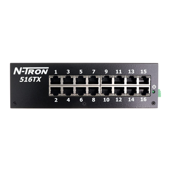
Front Panel From Left to Right: Link LED for Fiber Optic Port (only FX/FXE models) 100MB/s Fiber Optic TX Port (only FX/FXE models) 100MB/s Fiber Optic RX Port (only FX/FXE models) Activity LED for Fiber Optic Port (only FX/FXE models) RJ45 Ports Auto sensing 10/100 BaseTX Connections Green LED lights when Power is connected NOTE: Each RJ45 data port has two LED‟s located at the top or bottom of each connector. -
Page 13: Applying Power (Side View)
DC Voltage sources. Use wire sizes 16-28 gauge. The power cord should be limited to less than 10 meters in order to ensure optimum performance. Recommended 24V DC Power Supplies, similar to 100VAC/240VAC: N-Tron‟s NTPS-24-1.3, DC 24V/1.3A. Note: For 526FX2 please use the NTPS-24-3, DC 24V/3.0A (Revised 2011-07-13) -
Page 14: N-Tron Switch Grounding Techniques
(i.e. CE) are obtained when the N-Tron switch chassis is connected to earth ground via a drain wire. Some N-Tron switches have metal din-rail brackets that can ground the switch if the din-rail is grounded. In some cases, N-Tron switches with metal brackets can be supplied with optional plastic brackets if isolation is required. -
Page 15: Rj45 Connector Crimp Specifications
RJ45 Connector Crimp Specifications Please reference the illustration below for your Cat5 cable specifications: (Revised 2011-07-13) -
Page 16: Connecting The Unit
Serial Cable Connect the serial COM port of your PC and the 500 Series Switch using a standard straight through cable. You will require a cable with a 9-pin or 25-pin sub-D female connector for the PC end, and a 9-pin male sub-D connector for the series 500 end. -
Page 17: Troubleshooting
5. Verify that cabling is Category 5E or greater for 100Mbit Operation. 6. For FX/FXE models, verify TX is connected to far end RX and vise versa. Also insure the connecting partner is 100Mb/s IEEE 100BaseFX compliant. Note: the 500 Series FX/FXE switches do not support the 10BaseFL standard. -
Page 18: Command Line Interpreter
Ethernet switch using a command line interpreter. These functions may be accessed using the serial port (marked COM). To access the Command Line Interpreter (CLI), connect a PC serial port to the 500 Series V24 serial port and use HyperTerminal or equivalent. -
Page 19: Logging In (Password Protection)
Logging In (password protection) Access using the CLI is password-protected. You can log in as administrator to read and modify the 500 Series switch parameters. Note: The factory defaults admin password is admin. First press <Escape> to access the Management Console Function. enter username „admin‟... -
Page 20: Cli Tree Of Menus
CLI Tree of Menus info (Show identification data) SYSTEM (Open system menu) nview (Get information about N-View function) info (Get information about N-View) enable/disable (Enable/Disable N-View) aging (Aging Time for dynamically learned addresses) info (Get information about Aging) ... - Page 21 (SWITCH Sub-Menu Continued) igmp (IGMP Snooping) info (Get information about IGMP Snooping) enable/disable (Enable/Disable IGMP Snooping) routers (Manage Router Port(s) for IGMP Snooping) 'A' to Auto-detect plus manual, OR 'M' for Manual only, OR 'N' for None.
-
Page 22: Cli Menus And Commands
Example of the (top level) info screen: CLI>info Self Test & System Initialization Complete..OK! N-TRON Industrial Ethernet Switch - Model Number: 524 TX-A. N-Tron firmware version : 8.01 Copyright (c) 2005 N-TRON MAC ADDRESS:00-07-AF-00-05-24 N-View is ENABLED. -
Page 23: System Menu
System Menu Command Description Comment nview Get information about N-View function. aging Set and get info on Aging Time for dynamically learned addresses info Displays the current system status. (info for LINK Status. Rate, Flow, etc. 508/9)(info1,2 for 516/7) info1, info2,... (info1,2,3,4 for 524) (info1,2,3,4 for 526) upwd... -
Page 24: Aging Menu
Aging Menu When enabled, the Aging Time for dynamically learned addresses can be set from 10 to 300 seconds. The default is 300 seconds, except it is 20 seconds for 508FX2 and 526FX2. Cycling power clears the learned addresses. The configuration console is only available with –A models. Note: On –N and basic (no dash) units, aging is enabled and uses the defaults above without the option for reconfiguration. -
Page 25: System Info
System Info System info provides information on each port, as shown in the example below. Note that this is real time status, and some parameters (such as Rate, Duplex, and Crossover) will oscillate if not linked and not forced. To see forced settings, go to switch/ports/info. Example of a system „info‟... -
Page 26: User Password
The user password feature is available in firmware version 8.09 and subsequent. For security reasons forgotten passwords can only be reset to factory defaults with the physical return of the switch to N-TRON or to an authorized N-TRON distributor. CLI\SYSTEM>upwd Enter User password (4 to 8 characters), or <(ESC)>... -
Page 27: Switch Menu
Note: With port mirroring enabled, the 500 series switch will forward the traffic (ingress, egress, or both) from the source port to the destination port. Note that this results in mirrored packets being transmitted out the destination port even though the source and destination addresses of that packet are not associated with that port. - Page 28 Example of the Mirroring config screen: CLI\SWITCH\MIRROR>config Configure MIRROR Function For Port Mirroring, the Source Port is now: 17 Select Source Port [1...26] : Enter Port Number (or ESC to exit):5 For Port Mirroring, the Source Port is now: 5 For Port Mirroring, the Destination Port is now: 'out of range' Select Destination Port, one of: 1 2 3 4 6 7 8 25 Enter Port Number (or ESC to exit):9...
-
Page 29: Mac Based Trunking
Notes on Trunking: Mirroring overrides trunking (does mirror on the other trunk line). Can be used together carefully. Functionality, when trunking is enabled, on the 500 series is: If Trunk Groups 1 & 2 are both Activated: o Ports 1 &... - Page 30 Example Configuration for 508/509 Trunking: Port 1 Port 2 508TX-A -or- 509FX-A Port 3 Port 4 Trunking Port 5 Enabled Port 6 Group 2 Activated If 509FX-A, Fiber (port 9) Port 7 Port 8 Port 1 Port 2 508TX-A Port 3 Port 4 -or- 509FX-A...
-
Page 31: Qos
Example of the Trunking config screen: CLI\SWITCH\TRUNK>config Configure Trunking. Trunking is ENABLED. Trunk Group1 is now Active. Trunk Group2 is now Inactive. Enter: <(ESC)> to keep this configuration, 'A' to Activate both groups, 'D' to Deactivate both groups, '1' to activate Group1 and deactivate Group2, OR '2' to activate Group2 and deactivate Group1. - Page 32 Example of the Tagged QOS config screen: CLI\SWITCH\QOS>set_tag Configure Tagged QOS Threshold. The Tagged QOS threshold is now: 4 When an incoming 802.1p priority tag value is greater than or equal to this number, the incoming packet will be classified as high priority.
-
Page 33: Vlan
VLAN A local area network (LAN) is a private network usually confined to one plant. Virtual LANs (VLANs) allow a single physical LAN to be partitioned into several smaller logical LANs. VLANs are an effective means of portioning a larger LAN into manageable subsets. VLANs restrict the broadcast domain, improve performance and security, and they are ideal for isolating industrial automation systems from IT systems while retaining the plant's structural wiring. -
Page 34: Tagged Vlan
Tagged VLAN Tagged VLAN is in accordance with IEEE 802.1Q. When configuring each group: o choose VID ( 2-511 ranged on input) (except group1 is always VID=1) o choose member ports (any, all or none) o by port, choose if this is the primary VID for the port. o by port, for this group, choose if outgoing packets are untagged ( a port could tx untagged if one VID and tagged if another VID) When configuring untagged incoming packet handling:... - Page 35 When VLAN is enabled, all ports are members of VID 1 by default. If you enter „group2‟, for example, you‟ll be asked to enter (in decimal) a VLAN ID (VID) in the range of 1 through 511. Then, you‟ll be asked to enter the ports that are to participate in that tagged VLAN.
- Page 36 Example of the Tagged VLAN config ( groupX ) screen, not taking default choices: This example below chooses only some (not all) group ports to have the group VID as their PVID, and outgoing packets to be untagged for some (not all) group ports. CLI\SWITCH\VLAN>group7 Configure Tagged VLAN Group 7.
- Page 37 Example of tagged vlan info: CLI\SWITCH\VLAN>info Tagged VLAN is DISABLED. When enabled: Untagged pkts to these ports are discarded: 1 8 VLAN GROUP1 has VID= 1 and includes Ports: 7 8 9 10 11 12 13 14 15 16 GROUP1 outgoing pkts are untagged for ports: 7 8 9 10 11 12 13 14 15 16 VLAN GROUP2 has VID=215 and includes Ports: 2 6 17 GROUP2 outgoing pkts are untagged for ports: 2 6 17 VLAN GROUP7 has VID=325 and includes Ports: 1 2 3 4 5 6 17...
- Page 38 Tagged VLAN Example scenario: This example illustrates a case where all devices attached to the switch are VLAN unaware, except the „feed‟ from another switch or router on port 1. All devices on this switch are in VLAN VID=4, which is unique in a topology that includes multiple switches.
- Page 39 Tagged VLAN Example scenario: ( continued from previous sheet) CLI\SWITCH\VLAN>info Tagged VLAN is ENABLED. Untagged pkts to these ports are discarded: 1 VLAN GROUP1 has VID= 1 and includes Ports: none GROUP1 outgoing pkts are untagged for ports: none VLAN GROUP2 has VID= 4 and includes Ports: all GROUP2 outgoing pkts are untagged for ports: 2 3 4 5 6 7 8 9 10 11 12 13 14 15 16 17 There is more.
-
Page 40: Port Vlan
Port VLAN Port VLAN is accomplished entirely within the switch itself. All incoming frames can be untagged, or if tagged the tag will be replaced by the PVID (see explanation above). Incoming packets will use the (internal to the switch) PVIDs to determine group membership. All outgoing frames will be untagged. All unlearned packets will flood only to all group member ports. - Page 41 Example of the Port VLAN config ( groupX ) screen, not taking default choice for PVID: This example below chooses only some (not all) group ports to have the group VID as their PVID. CLI\SWITCH\VLAN>group4 Configure Port VLAN Group 4. Enter ports to Join VLAN Group 4 (Example: '3,6,12,14<enter>'.) Enter Port Numbers (or ESC to exit)>...
- Page 42 Port VLAN Example scenario : ports 1,2,3 - control system (only communicate with each other and the 2 PC's) ports 4,5 - PCs (each communicate with all ports 1 thru 9) ports 6,7,8,9 office system (only communicate with each other and the 2 PC's) For example: TX 7 to 3 and no ports RX.
- Page 43 Port VLAN Example scenario: ( continued from previous sheet) CLI\SWITCH\VLAN>group4 Configure Port VLAN Group 4. Enter ports to Join VLAN Group 4 (Example: '3,6,12,14<enter>'.) Enter Port Numbers (or ESC to exit)> 1,2,3,4,5,6,7,8,9 Would you like all these ports to have PVID=4 ? Enter 'NO' or (YES): CLI>no Enter ports to have PVID=4...
-
Page 44: Igmp Snooping
The Internet Group Management Protocol (IGMP) is a protocol that provides a way for a computer to report its multicast group membership to adjacent „routers‟. In this case N-Tron 500 series –A switches provide router-like functionality. Multicasting allows one computer to send content to multiple other computers that have identified themselves as interested in receiving the originating computer's content. - Page 45 Example of entering manually selected routers in auto-detect plus manual: ( One does not have to manually enter anything for IGMP SNOOPING, unless accommodating non-IGMP devices.) Enter A, M, N , (or ESC to exit) > a For IGMP Snooping, router ports mode is auto. Manually Selected Router Port(s): none Automatically detected Router Port(s): none Would you like to change that ? Enter 'YES' or (NO):...
- Page 46 “Source IP” for the Query frame, when you select Query On or Auto, you will be shown the calculated address and asked if you‟d like to change it (yes or no). In 500 series switches, the “IGMP Query Source IP Address” is only for IGMP purposes. It cannot be „pinged‟, for example.
- Page 47 Example of an IGMP info screen (without cycling power, <ESCAPE>, SWITCH, IGMP, INFO): CLI\SWITCH\IGMP>info IGMP Snooping is ENABLED. When power is cycled: Query mode is auto. Query Frame Source IP: 191.23.12.15. Received Lower Query Frame Source IP: 10.10.10.5. For IGMP Snooping, router ports mode is auto. Manually Selected Router Port(s): 3 17 Automatically detected Router Port(s): 4 5 Rfilter is applied to these ports: 5 8 17...
-
Page 48: Filters
After entering „sfilter‟, you will be asked to enter the “static multicast filter number (1 ->16)” ( for 524/526) or “static multicast filter number (1 ->12)” ( for other 500 series products) and then to “Enter 12 digit Address (Ex. '01005e0a0a0a<enter>'), or all zeroes to disable the group”. - Page 49 Note that IGMP Snooping operates dynamically and with or without these static filter entries. Note that vlan must be disabled before enabling any „bfilter‟s. Example of the Filters bfilter screen: CLI\SWITCH\FILTERS>bfilter Enter ports that are to receive General Broadcast frames > Use commas to separate port numbers.
- Page 50 Example of the Filters info screen (508FX2-A ONLY): CLI\SWITCH\FILTERS>info CLI\SWITCH\FILTERS>info The General Broadcast filter is enabled now. These ports receive General Broadcast: 1 2 3 4 5 6 7 8 N-Ring filter is Enabled. Ports 7 and 8 are ring ports. 600 series ring filter is Enabled.
- Page 51 Step2: Map those 23 bits into the low order 23 bits of a MAC address with the fixed high order 25 bits of the IEEE multicast addressing space prefixed by 01:00:5E. An example of this process is shown below. This example assumes that the application has selected the IP class D address 239.1.1.10 and demonstrates the mapping of the low order 23 bits of the class D IP address to the low order bits of the MAC layer destination.
-
Page 52: Ports
( We have seen a case where the wiring was cat3 and the devices autonegotiated to 100/full, but the wiring would not support it.) On the 500 series, one can autonegotiate, or one can force to any of 4 modes: 100 full, 100 half, 10 full, or 10 half. - Page 53 Each time you select a forced port function (speed, duplex, or crossover) the ports you enter next are the complete new set of ports for that function. For example, if you enter „speed10‟, then respond with only <enter> (no ports) to the prompt “Enter forced 10 Mb ports:”, then no ports in the switch will be forced to 10 Mb, regardless of prior history.
- Page 54 CLI\SWITCH\PORTS>link10h Enter ports to advertise 10Mb and half duplex: Use commas to separate port numbers. (Example: '3,6,12,14,22<enter>'.) Enter Port Numbers (or ESC to exit):12,13 CLI\SWITCH\PORTS> Example of the Ports filter screen: CLI\SWITCH\PORTS>filter The threshold for collision filter management is 10 collisions in 20 seconds. Would you like to change it ? Enter 'YES' or (NO): CLI>...
-
Page 55: 500 Series Stacked Switches Igmp Multicast Limitations
( Reference the figure below. ) 3. In stage 1, all ports of any 500 series ‟–A‟ switch may be connected to multicasting devices. NOTE: A fiber ring, backbone, or trunked architecture is basically stage 1 for these purposes. -
Page 56: With Quality Of Service (Qos) Enabled, Which Would Have To Be Manually Configured
( Reference the figure below. ) 3. In stage 1, all ports of any 500 series ‟–A‟ switch may be connected to multicasting devices. NOTE: A fiber ring, backbone, or trunked architecture is basically stage 1 for these purposes. -
Page 57: Key Specifications (508Tx)
Key Specifications (508TX) Switch Properties Number of MAC Addresses 4,000 Aging Time Programmable 2.2 s Latency Min. Backplane Speed 2.6Gb/s Switching Method Store & Forward Physical Height: 2.3" Width: 5.5" Depth: 3.5" Weight: 1.6 lbs Din-Rail: 35mm Electrical Redundant Input Voltage: 10-30 VDC Input Current: 200 mA @ 24VDC (max current 0.5 A) -
Page 58: Damp Heat: Iec60068-2-30 (Test Db)
IEEE 1613 (V.S.4 150 mm/s) IEC60068-2-6 (Test Fc) Cold: IEC60068-2-1 Dry Heat: IEC60068-2-2 Damp Heat: IEC60068-2-30 (Test Db) GOST-R Certified. Warranty: Effective January 1, 2008, all N-TRON products carry a 3 year limited warranty from the date of purchase. (Revised 2011-07-13) -
Page 59: Key Specifications (508Fx2/Fxe2)
Key Specifications (508FX2/FXE2) Switch Properties Number of MAC Addresses 4,000 Aging Time Programmable 2.2 s Latency Min. Backplane Speed 2.6Gb/s Switching Method Store & Forward Physical Height: 2.3" Width: 5.9" Depth: 3.8" Weight: 1.7 lbs Din-Rail: 35mm Electrical Redundant Input Voltage: 10-30 VDC Input Current: 380 mA @ 24VDC (max current 1.0 A) - Page 60 IEEE 1613 (V.S.4 150 mm/s) IEC60068-2-6 (Test Fc) Cold: IEC60068-2-1 Dry Heat: IEC60068-2-2 Damp Heat: IEC60068-2-30 (Test Db) GOST-R Certified. Warranty: Effective January 1, 2008, all N-TRON products carry a 3 year limited warranty from the date of purchase. (Revised 2011-07-13)
-
Page 61: Key Specifications (509Fx/Fxe)
Key Specifications (509FX/FXE) Switch Properties Number of MAC Addresses 4,000 Aging Time Programmable 2.2 s Latency Min. Backplane Speed 2.6Gb/s Switching Method Store & Forward Physical Height: 2.3" Width: 5.5" Depth: 3.5" Weight: 1.6 lbs Din-Rail: 35mm Electrical Redundant Input Voltage: 10-30 VDC Input Current: 260 mA @ 24VDC (max current 0.5 A) -
Page 62: Gost-R Certified
IEEE 1613 (V.S.4 150 mm/s) IEC60068-2-6 (Test Fc) Cold: IEC60068-2-1 Dry Heat: IEC60068-2-2 Damp Heat: IEC60068-2-30 (Test Db) GOST-R Certified. Warranty: Effective January 1, 2008, all N-TRON products carry a 3 year limited warranty from the date of purchase. (Revised 2011-07-13) -
Page 63: Key Specifications (516Tx)
Key Specifications (516TX) Switch Properties Number of MAC Addresses 4,000 Aging Time Programmable 2.2 s Latency Min. Backplane Speed 2.6Gb/s Switching Method Store & Forward Physical Height: 2.3" Width: 7.4" Depth: 3.5" Weight: 1.9 lbs Din-Rail: 35mm Electrical Redundant Input Voltage: 10-30 VDC Input Current: 400 mA @ 24VDC (max current 1.0 A) -
Page 64: Damp Heat: Iec60068-2-30 (Test Db)
IEEE 1613 (V.S.4 150 mm/s) IEC60068-2-6 (Test Fc) Cold: IEC60068-2-1 Dry Heat: IEC60068-2-2 Damp Heat: IEC60068-2-30 (Test Db) GOST-R Certified. Warranty: Effective January 1, 2008, all N-TRON products carry a 3 year limited warranty from the date of purchase. (Revised 2011-07-13) -
Page 65: Key Specifications (517Fx/Fxe)
Key Specifications (517FX/FXE) Switch Properties Number of MAC Addresses 4,000 Aging Time Programmable 2.2 s Latency Min. Backplane Speed 2.6Gb/s Switching Method Store & Forward Physical Height: 2.3" Width: 7.4" Depth: 3.5" Weight: 1.9 lbs Din-Rail: 35mm Electrical Redundant Input Voltage: 10-30 VDC Input Current: 440 mA @ 24VDC (max current 1.0 A) -
Page 66: Damp Heat: Iec60068-2-30 (Test Db)
IEEE 1613 (V.S.4 150 mm/s) IEC60068-2-6 (Test Fc) Cold: IEC60068-2-1 Dry Heat: IEC60068-2-2 Damp Heat: IEC60068-2-30 (Test Db) GOST-R Certified. Warranty: Effective January 1, 2008, all N-TRON products carry a 3 year limited warranty from the date of purchase. (Revised 2011-07-13) -
Page 67: Key Specifications (524Tx)
Key Specifications (524TX) Switch Properties Number of MAC Addresses 4,000 Aging Time Programmable 2.2 s Latency Min. Backplane Speed 2.6Gb/s Switching Method Store & Forward Physical Height: 1.8" Width: 19" Depth: 4.3" Weight: 3.7 lbs Electrical Redundant Input Voltage: 10-30 VDC Input Current: 720 mA @ 24VDC (max current 1.0 A) Inrush Current:... -
Page 68: Damp Heat: Iec60068-2-30 (Test Db)
IEEE 1613 (V.S.4 150 mm/s) IEC60068-2-6 (Test Fc) Cold: IEC60068-2-1 Dry Heat: IEC60068-2-2 Damp Heat: IEC60068-2-30 (Test Db) GOST-R Certified. Warranty: Effective January 1, 2008, all N-TRON products carry a 3 year limited warranty from the date of purchase. (Revised 2011-07-13) -
Page 69: Key Specifications (526Fx2/Fxe2)
Key Specifications (526FX2/FXE2) Switch Properties Number of MAC Addresses 4,000 Aging Time Programmable 2.2 s Latency Min. Backplane Speed 2.6Gb/s Switching Method Store & Forward Physical Height: 1.8" Width: 19" Depth: 4.3" Weight: 3.7 lbs Electrical Redundant Input Voltage: 10-30 VDC Input Current: 720 mA @ 24VDC (max current 1.0 A) Inrush Current:... - Page 70 IEEE 1613 (V.S.4 150 mm/s) IEC60068-2-6 (Test Fc) Cold: IEC60068-2-1 Dry Heat: IEC60068-2-2 Damp Heat: IEC60068-2-30 (Test Db) GOST-R Certified. Warranty: Effective January 1, 2008, all N-TRON products carry a 3 year limited warranty from the date of purchase. (Revised 2011-07-13)
- Page 71 N-TRON, Corp. warrants to the end user that this hardware product will be free from defects in workmanship and materials, under normal use and service, for the applicable warranty period from the date of purchase from N-TRON or its authorized reseller. If a product does not...
Need help?
Do you have a question about the 500 Series and is the answer not in the manual?
Questions and answers