Campbell CS120A Instruction Manual
Visibility and present weather sensors
Hide thumbs
Also See for CS120A:
- Product manual (77 pages) ,
- User manual (62 pages) ,
- Installation manual (18 pages)

Subscribe to Our Youtube Channel
Related Manuals for Campbell CS120A


Summary of Contents for Campbell CS120A
- Page 1 CS120A and CS125 Visibility and Present Weather Sensors Issued: 6.11.17 Copyright © 2013-2017 Campbell Scientific Ltd. CSL 1141...
- Page 3 Quotations for repairs can be given on request. It is the policy of Campbell Scientific to protect the health of its employees and provide a safe working environment, in support of this policy a “Declaration of Hazardous Material and Decontamination”...
- Page 5 Campbell Scientific Ltd can advise on the recycling of the equipment and in some cases arrange collection and the correct disposal of it, although charges may apply for some items or territories.
- Page 7 • Periodically (at least yearly) check electrical ground connections. WHILE EVERY ATTEMPT IS MADE TO EMBODY THE HIGHEST DEGREE OF SAFETY IN ALL CAMPBELL SCIENTIFIC PRODUCTS, THE CUSTOMER ASSUMES ALL RISK FROM ANY INJURY RESULTING FROM IMPROPER INSTALLATION, USE, OR MAINTENANCE OF TRIPODS, TOWERS, OR ATTACHMENTS TO TRIPODS AND TOWERS...
-
Page 9: Table Of Contents
7.3 Optional Campbell Scientific Mount ............15 8. Sensor internal connectors’ description ....17 8.1 Sensor recommended wiring using Campbell Scientific cables ..... 19 9. CS215 T/RH Sensor (CS125 only) ......21 10. Functions of the internal switches ......22... - Page 10 11. Message Formats: A breakdown of the different default outputs of the sensor – Basic/Partial/Full ..........24 11.1 Visibility only messages ............... 24 11.2 Messages with SYNOP Present Weather Codes (CS125 only) .... 25 11.3 Messages with METAR Present Weather Codes (CS125 only) ... 26 11.4 Messages with Generic SYNOP Present Weather Codes (CS125) ..
- Page 11 Appendices A. Sensor Block Diagram ........... A-1 B. Example C code of the checksum CRC-16 ... B-1 C. Example CRBasic programs ......... C-1 D. Present Weather Codes ........D-1 Figures 1-1 Particles in the sample volume scatter light in all directions, including into the detector ..................
-
Page 13: Introduction
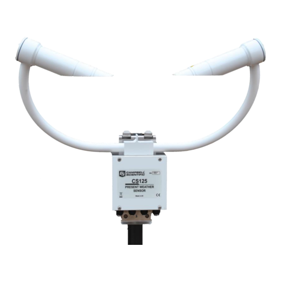
The CS120A is a visibility sensor. The CS125 additionally detects and reports present weather in the form of SYNOP, METAR or NWS codes. The CS125 has the same specification for visibility measurement as the CS120A. It is possible to upgrade a CS120A to a CS125, please contact Campbell Scientific for more details. -
Page 14: General Safety
CS120A and CS125 Visibility and Present Weather Sensors 1.1 General Safety This manual provides important safety considerations for the installation, operation and maintenance of the sensor. These safety considerations are classified into three levels: WARNING Warnings alert the installer or user to serious hazards. -
Page 15: Principle Of Operation
Figure 1-1. Particles in the sample volume scatter light in all directions, including into the detector The CS120A and CS125 comprise an emitter and detector aligned as in Figure 1-1. The emitter produces a beam of near infra-red light pulsed at 1 kHz. A detector has a field of view which overlaps the beam and is inclined at 42 degrees to it. -
Page 16: Signals From Large, Slow Falling Snowflakes And Smaller, Faster, Raindrops
CS120A and CS125 Visibility and Present Weather Sensors Figure 1-2. Signals from large, slow falling snowflakes and smaller, faster, raindrops The CS125 also has a temperature sensor. These 3 parameters, fall speed, size and temperature are used to identify the type of particle. If an additional external temperature and relative humidity probe is connected then a wet-bulb temperature can be calculated. -
Page 17: Recommended Tools
The sensor is shipped set to the following default communication RS-232, 8N1, 38400 baud, a sensor ID = 0 and set to transmit default messages, full format, visibility only for the CS120A, SYNOP present weather full format for the CS125, at 1 minute intevals (see Section 11). -
Page 18: Measurement Specification
CS120A and CS125 Visibility and Present Weather Sensors 2. Measurement specification Minimum Nominal Maximum Value Value Value Visibility characteristics Reported visibility (metric) 5 metres 75,000 metres Reported visibility (imperial) 16 feet 46 miles Visibility accuracy calibration +/- 2% against factory calibration disk... -
Page 19: Optical Specification
Instruction Manual Hood heater power supply Hood heater voltage (AC or DC) Hood heater wattage (at 24V AC or User alarm outputs User output high level (at 85ºC) 3.8V User output high level (at 25ºC ) 4.13V User output low (All temperatures) 0.25V 0.55V User output current... -
Page 20: Communications Specification
CS120A and CS125 Visibility and Present Weather Sensors 4. Communications specification 4.1 Communications electrical specifications Minimum Nominal Maximum Value Value Value RS-232 Communications RS-232 input threshold Low 0.8V 1.5V RS-232 input threshold High 2.0V 2.4V RS-232 input absolute maximum -15V... -
Page 21: Environmental Specifications
Hood heater Turn Off >25°C Extended temperature ranges are only guaranteed if the sensor has been tested by Campbell Scientific and verified within this temperature range. Some degradation of absolute accuracy can be expected at the extremes of the extended ranges. -
Page 22: Mechanical Specifications
CS120A and CS125 Visibility and Present Weather Sensors 6. Mechanical specifications 6.1 Dimensions 6.2 Weights Sensor weight: 3 Kg Shipping weight: 6 Kg (including packing box) 6.3 Mounting Sensor mounting: Bracket mounts on a vertical pole 32-52.5 mm diameter. The mounting bracket has cut-outs for band clamps for larger diameter masts. - Page 23 Instruction Manual The descriptions in this section are not exhaustive. Please refer to NOTE meteorological publications for further information on locating weather instruments The sensor should be sited in a position representative of local weather conditions and not of a specific microclimate (unless the analysis of microclimate weather is being sought).
-
Page 24: Equipment Grounding
CS120A and CS125 Visibility and Present Weather Sensors If operating a sensor indoors it is likely that there will be sources of NOTE light and/or reflections that will create false readings and erratic results. NOTE If carrying out simple checks, blocking a lens or the sample volume will simulate an INCREASE in visibility not a decrease. - Page 25 Instruction Manual distance from the sensor. The power supply enclosure should be mounted away from the sensor head to avoid wind flow disturbance or rain drops bouncing back up into the sensor’s sensing volume. Take care not to overtighten the nuts on the bolts, as it may CAUTION be possible to distort and/or damage the brackets or DSP plate by doing so, and/or the nuts may seize up.
- Page 26 CS120A and CS125 Visibility and Present Weather Sensors Figure 7-4. Mounting to a flat surface Slots are provided to allow band clamps to be used with larger diameter masts, see Figure 7-5. Figure 7-5. Use of band clamps...
-
Page 27: Optional Campbell Scientific Mount
Instruction Manual 7.3 Optional Campbell Scientific Mount A Campbell Scientific `optical sensor mount’, part number 009354, is available. This will put the sample volume at about 1.5 m in compliance with the WMO `Guide to Meteorological Instruments and Methods of Observation’, 7 Edition, Section 9.3.4. - Page 28 CS120A and CS125 Visibility and Present Weather Sensors Drill four 12 mm diameter holes using the mount base as a template or following the drawing below to a depth of 77 mm. Figure 7-7. Mounting footprint Clean the holes of all debris.
-
Page 29: Sensor Internal Connectors' Description
CAUTION 10 m is the longest length of the cable type supplied recommended. particular, additional RS-485 communication should be twisted pair. Please contact Campbell Scientific if you wish to use a longer length of cable. Figure 8-1. Connections... - Page 30 To use these connections it is necessary to either use the cable gland taking the hood heater power or, if the hood heater is also required, to use different cables to those supplied. Please contact Campbell Scientific if you need any advice on choice of cable.
-
Page 31: Sensor Recommended Wiring Using Campbell Scientific Cables
9 pin D-connector (DB9). The D- connector can be connected directly to a PC or to a datalogger such as the Campbell Scientific CR1000 using a suitable interconnecting cable such as the SC110. If another type of connection is required then the D-connector should be removed. -
Page 32: Communications And Power Connector
CS120A and CS125 Visibility and Present Weather Sensors Figure 8-3. Communications and power connector Two types of configuration cable are available from Campbell Scientific that plug directly into connector B in place of the normal connector and cable. One has a RS-232 or RS-485 output according to how the CS120A/CS125 is configured (Figure 8-4) and one has a USB output (Figure 8-5). -
Page 33: Cs215 T/Rh Sensor (Cs125 Only)
Instruction Manual 9. CS215 T/RH Sensor (CS125 only) The CS125 has a temperature sensor mounted in the crossarm that is used in determining precipitation type. A CS215 temperature and RH sensor can be connected to a CS125. This is recommended as it will improve the performance of the CS125 in identifying precipitation and allows it to, for example, distinguish between mist and haze. -
Page 34: Functions Of The Internal Switches
CS120A and CS125 Visibility and Present Weather Sensors CS215 WIRING COLOUR FUNCTION +12V Green SDI-12 Black Power Ground Clear Shield White Power Ground 3 or NC Figure 9-1. Connection for the optional CS215 T/RH sensors 10. Functions of the internal switches The sensor is equipped with four switches located within the main enclosure. -
Page 35: Internal Switches
Instruction Manual Figure 9-2. Internal switches Internal switch functions Switch number Function Reserved for future use, set to OFF. When switched to the ON position and the sensor is power cycled this switch temporarily sets the sensor communications port to a default RS-232 communication state at 38400 baud. -
Page 36: Message Formats: A Breakdown Of The Different Default Outputs Of The Sensor - Basic/Partial/Full
(see Section 15 on how to set default outputs). The SYNOP Full Format message is the default message for the CS125 and the Full Format Visibility only message is the default for the CS120A. NOTE STX and ETX are hexadecimal command characters. -
Page 37: Messages With Synop Present Weather Codes (Cs125 Only)
Instruction Manual Partial Format, Visibility Only Full Format, Visibility Only (Default message for CS120A) 11.2 Messages with SYNOP Present Weather Codes (CS125 only) SYNOP Present Weather Basic Format SYNOP Present Weather Partial Format... -
Page 38: Messages With Metar Present Weather Codes (Cs125 Only)
CS120A and CS125 Visibility and Present Weather Sensors SYNOP Present Weather Full Format (Default message for CS125) 11.3 Messages with METAR Present Weather Codes (CS125 only) METAR Present Weather Basic Format METAR Present Weather Partial Format... -
Page 39: Messages With Generic Synop Present Weather Codes (Cs125)
Instruction Manual METAR Present Weather Full format *Note: relative humidity is only available if a CS215 temperature and RH sensor is attached. If not this field is “-99”. 11.4 Messages with Generic SYNOP Present Weather Codes (CS125 only) These messages include simplified, generic present weather codes such as 70 for snow which may be required for some data collection systems. - Page 40 CS120A and CS125 Visibility and Present Weather Sensors Generic SYNOP Present Weather Partial format Generic SYNOP Present Weather Full format Message ID break down Definition Basic format. Contains only distance and system information Partial format. Contains user alarm outputs Full format. Contains all system alarms codes...
- Page 41 Instruction Manual Sensor ID break down Definition Unit number defined by the user to aid identification of data. Zero by default. Useful for RS-485 networks. Operates as an address in RS-485 mode System status break down Status level Definition No fault Possible degraded performance Degraded performance Maintenance required...
- Page 42 CS120A and CS125 Visibility and Present Weather Sensors System alarms break down Alarm Range Severity Definition Emitter failure 0 = Everything is within normal parameters (emitter hoods 1 = Light output level too low main LED 2 = Light output level too high...
-
Page 43: Example Sensor Message Outputs
*CS125 only, see Appendix. 11.5 Example sensor message outputs Full format, visibility only (CS120A default) 2 0 0 10 9622 M 1 0 0 0 0 0 0 0 0 0 0 0 0 46AA SYNOP present weather full format (CS125 deault) -
Page 44: Custom Message Format
ABCD is the checksum 11.6 Custom message format The custom message format allows the CS120A/CS125 message to be modified to meet particular requirements. The custom message contains a fixed basic set of variables and up to 16 additional fields. (Note: the custom message output is only available on OS7 and above). - Page 45 Instruction Manual Return to the message menu and select option 7. You will now be presented with the list of options shown below: CS125 MESSAGE - SUB 4 Configure the message output format: 1 - Averaging duration 2 - User alarms 3 - System alarms 4 - Dirty windows values 5 - Sensor serial number...
-
Page 46: Interface Methods - Device Configuration Utility/Command Line/Menu
Utility/Command line/Menu The sensor can be set up and controlled in one of three ways. The first method is by using Campbell Scientific’s Device Configuration Utility Software (DevConfig) which is included with each delivery on the manuals/ resource disk. This software allows an easy menu driven interface for configuring the sensor on any Microsoft™... -
Page 47: Configuring A Pc For Talking To The Sensor
12.1 Configuring a PC for talking to the sensor Described below is the procedure for setting up communications using a terminal emulator program. The terminal emulators built into many Campbell Scientific software products can also be used. The following settings should then be used by default:... - Page 48 CS120A and CS125 Visibility and Present Weather Sensors User Alarm 2 Enabled User alarm two activation state 0 = Alarm two disabled 1 = Alarm two enabled 0 = Check if distance is less than ‘User alarm 2 User Alarm 2 Active Distance’...
-
Page 49: Command Line Mode
Instruction Manual Dew heater override 0 = Allow the sensor to automatically control the dew heaters 1 = Turn the dew heaters off Hood heater override 0 = Allow the sensor to automatically control the hood heaters 1 = Turn the hood heaters off Dirty window 0 = No compensation applied compensation... -
Page 50: Example Of A Set Command
CS120A and CS125 Visibility and Present Weather Sensors SET transmitted data Example Description 0x02 STX ^ B Delimiting character Current Sensor ID Delimiting character Sensor ID (may be a new ID) User Alarm 1 Set User Alarm 1 Active User Alarm 1 Distance... -
Page 51: Example Of A Setnc Command
Instruction Manual 14.2.1 Example of a SETNC Command SETNC:0:0 1 1 1000 1 0 15000 2 0 M 60 1 2 0 1 1 0 0 0 1 7 80 :XXXX: 14.3 The MSGSET Command The user customisable message format can be configured using the MSGSET command. - Page 52 CS120A and CS125 Visibility and Present Weather Sensors 0800 NWS code 0400 METAR code 0200 SYNOP code 0100 Generic SYNOP 0080 Accumulation 0040 Intensity 0020 Particle count 0010 Sensor serial number 0008 Dirty windows values 0004 System alarms 0002 User alarms...
-
Page 53: The Get Command
Instruction Manual The message sent is: MSGSET:0:161C:9794: The response is: 161C 7067 In this case “7067” is the checksum 14.4 The GET Command The GET command retrieves settings data from the sensor, including message format data and user alarm settings amongst others. This command does not retrieve visibility or environmental information from the sensor. - Page 54 CS120A and CS125 Visibility and Present Weather Sensors Data returned by the GET command GET returned data Example Description 0x02 Sensor ID User Alarm 1 Set User Alarm 1 Active (0 = less than) User Alarm 1 Distance User Alarm 2 Set...
- Page 55 Instruction Manual Example of a GET returned data 0 0 0 10000 0 0 10000 2 1009 M 30 0 2 1 1 1 0 0 0 1 11.5 80 D4FD Explanation: Sensor ID = 0 User Alarm 1 not set User Alarm 1 not active User Alarm 1 distance = 10000 metres User Alarm 2 not set...
-
Page 56: The Msgget Command
CS120A and CS125 Visibility and Present Weather Sensors 14.5 The MSGGET Command The Message Get (MSGGET) command retrieves the current settings of the custom message from the sensor. MSGGET command transmitted data Example Description (Hex) 0x01 Delimiting character MSGGET MSG GET... -
Page 57: The Poll Command - Polling The Sensor
Instruction Manual 14.6 The POLL command – Polling the sensor The POLL command requests the current visibility and/or alarm conditions from the sensor. The output format of this command depends on how the sensor is configured using the SET command or the menu interfaces. The POLL command POLL command transmitted data Example... -
Page 58: The Accres Command - Resetting The Accumulation Value
CS120A and CS125 Visibility and Present Weather Sensors 14.7 The ACCRES command – Resetting the accumulation value If accumulation is included in a custom message the ACCRES command resets the accumulation to zero. See Section 11.6. The ACCRES command ACCRES command transmitted data... - Page 59 The ‘open 0’ command is not normally echoed. NOTE The terminal menu only gives access to more common settings. The following text should now be displayed: WELCOME TO THE CAMPBELL SCIENTIFIC LTD CS125 SETUP MENU ID 0 S/N 2003 (1) Message output menu...
- Page 60 The messages are described in more detail in Section 11. The CS120A can only output messages 0-2 and a limited custom message. CS125 MESSAGE - SUB 3 Set the message output format. Current format is: FULL...
- Page 61 Instruction Manual Menu 3: The calibration menu CS125 CALIBRATION - MENU 3 ID 0 S/N 1003 (1) Perform calibration (2) Restore the factory calibration (3) Perform dirty windows zero offset calibration (4) Restore dirty windows factory calibration (9) Refresh (0) Return to main menu ->...
- Page 62 (Section 18). If there is a flash error or signature error it is recommended that you contact Campbell Scientific. The sensor power down voltage shown before the supply voltage is not available for CS120A sensors with serial numbers less than E1030.
- Page 63 Instruction Manual Menu 5: The communication menu CS125 COMMUNICATIONS - MENU 5 ID 0 S/N 1009 (1) Set sensor ID (2) Set RS-232/RS-485 baud rate:38400 (3) Toggle RS-232/RS-485 modes:RS-232 (9) Refresh (0) Return to main menu -> The communications menu is used to set baud rates and the mode of operation (RS-232/RS-485).
-
Page 64: Calibrating The Sensor
The sensor can be checked and adjusted using the optional sensor high grade calibration kit part number 010805. The calibration must be run using the onboard menu system. If you have Campbell Scientific’s Device configuration program a terminal emulation screen is provided in the sensor screens to let you access this function. - Page 65 Instruction Manual Select option 1 to start the calibration. You will then be asked to confirm that you would like to perform a calibration. Please note, once you have entered yes at this point you will not be able to exit until the test is complete. However, power cycling the unit at this point will have no adverse effect on the sensor.
- Page 66 CS120A and CS125 Visibility and Present Weather Sensors CS120A/CS125 High grade calibrator serial number, extinction coefficient (EXCO) and equivalent MOR will be written here Figure 16-1. Calibration disk When you have entered the calibrator information the sensor will wait for you to place the foam bungs into the sensor hoods.
-
Page 67: Dirty Window Zero Calibration
Instruction Manual Figure 16-2. Mounting calibration disk Starting light level calibration. This test will take approximately two minutes. This part of the test will take approximately two minutes. Every ten seconds a dot should appear indicating that the test is progressing as normal. Calibration is now complete. -
Page 68: Internal Temperature Check (Cs125)
CS120A and CS125 Visibility and Present Weather Sensors To carry out the dirty window zero offset calibration make sure the windows are very clean. Temperature should ideally be in the range 15 – 30°C and the sensor should have been powered up for over 5 minutes. -
Page 69: Sensor Devconfig Download Instructions
Instruction Manual To use DevConfig to carry out an OS change requires RS-232 NOTE communication. If a sesor is set to communicate by RS-485 it can be temporarily set to RS-232 with switch 3 (see Section 10). Figure 17-1. Sensor DevConfig download instructions Figure 17-2. -
Page 70: Cleaning
Calibration is carried out at the factory and can be redone easily on site with the optional sensor calibrator or carried out by Campbell Scientific if required. Only general cleaning of the lenses is required to keep the sensor working efficiently. -
Page 71: Lubricating The Enclosure Screws
Instruction Manual 19. Lubricating the enclosure screws The sensor enclosure screws should be lubricated with a suitable anti-seize grease (often copper loaded) to protect the threads from corrosion. This should be reapplied when resealing the enclosure at regular intervals, normally after replacing the desiccant. - Page 72 CS120A and CS125 Visibility and Present Weather Sensors After the bags of desiccant have been allowed to cool in an airtight desiccator, they may be removed and placed in either an appropriate type polyliner tightly sealed to prevent moisture adsorption, or a container that prevents moisture from coming into contact with the regenerated desiccant.
- Page 73 Appendix A. CS120A/CS125 block diagram...
- Page 74 CS120A and CS125 Visibility and Present Weather Sensors...
- Page 75 Appendix B. Example C code of the CRC-16 checksum The code below is provided as an example for programmers implementing their own code to communicate with the sensor. Users using Campbell loggers can use the Checksum command in CRBasic to generate a CRC-16 checksum. Command: Checksum/ChkSumString,1,0).
- Page 76 CS120A and CS125 Visibility and Present Weather Sensors...
-
Page 77: Example Crbasic Programs
Appendix C. Example CRBasic programs C.1 CRBasic read program 'CR800 'Demonstration program to read data from a CS125 set to continuous output 'with the full SYNOP (default) message being transmitted 'Note: The CS125 emits this message every minute by default. Public Visibility 'These variables could be defined as DIM in a final program Public InString As String * 100 'Incoming string... - Page 78 CS120A and CS125 Visibility and Present Weather Sensors SerialInRecord(CS125_Comport,InString,&h02,0,&h03,NBytesReturned,01) 'Check that a message has been recieved first If NBytesReturned > 0 Then 'Split out the Data into strings SplitStr (SerialIndest(),InString," ",27,5) 'Check the received checksum is valid 'Calculate the expected checksum lngCRCCalc = CheckSum(InString,1,NBytesReturned-5) 'Extract the checksum from the message &...
- Page 79 Appendix C. Example CRBasic programs C.2 CRBasic POLL program 'CR800 'Demonstration program to read data from a CS125 set to polled output 'with the full SYNOP (default) message being transmitted 'Note: the sensor needs to be configured to behave like this, it is not setup by this program.
- Page 80 CS120A and CS125 Visibility and Present Weather Sensors 'Const CS125_Poll = CHR(2)&"POLL:8:0:939A:"&CHR(3)&CHR(13) 'address 8 'Const CS125_Poll = CHR(2)&"POLL:9:0:A4AA:"&CHR(3)&CHR(13) 'address 9 'Main Program BeginProg 'Open the logger serial port to which the CS125 is connected SerialOpen (CS125_Comport,38400,3,0,1000) Scan(10,Sec,1,0) 'The sensor is polled every 10 seconds SerialOut(CS125_Comport,CS125_Poll,"",0,100)
- Page 81 Appendix C. Example CRBasic programs C.3 Example CRBasic SET program '------------------------------------------------------------------------------- ' CS125 Visibility ' Program to test the SET command part of the command line interface on the CS125 ' Do not run this script for extended periods of time (days!) as it writes ' to flash over and over and will eventually wear the flash out ' Logger:CR1000 '-------------------------------------------------------------------------------...
- Page 82 CS120A and CS125 Visibility and Present Weather Sensors CheckVal = CheckSum (TempStringFunc,1,0) ' Use the CCITT CRC16 checksum ' Create final string going out to CS125 including start characters and end characters CS125CommandString = CHR(2) + TempStringFunc + ":" + FormatLong (CheckVal,"%04X") + ":"...
- Page 83 Appendix C. Example CRBasic programs C.4 Example CRBasic SETNC Command '------------------------------------------------------------------------------- ' CS125 Visibility ' Program to test the SETNC command part of the command line interface on the CS125 ' This command does not commit the settings to flash so settings will be lost if ' the sensor is power cycled ' This example uses a CS215 temperature and humidity probe to determine dew point.
- Page 84 CS120A and CS125 Visibility and Present Weather Sensors Dim CS125CommandString As String * 100 Dim i As Long Dim CheckVal As Long ' Create a string containing the values going out to the CS125 TempStringFunc = "SETNC:0:" For i = 1 To 21 TempStringFunc = TempStringFunc + CS125CArray(i) + "...
- Page 85 Appendix C. Example CRBasic programs 'CS215 Temperature & Relative Humidity Sensor measurements AirTC and RH SDI12Recorder(TRHData(),5,"0","M!",1,0) 'Calculate DewPoint DewPoint(TempDewPoint,AirTC,RH) ' Gather the current settings from the CS125 SerialFlush (Com1) TempString = "GET:0:0" CheckVal = CheckSum (TempString,1,0) ' Use the CCITT CRC16 checksum OutString = CHR(2) + TempString + ":"...
- Page 86 CS120A and CS125 Visibility and Present Weather Sensors C.5 Example CRBasic GET program '------------------------------------------------------------------------------- ' CS125 Visibility ' Program to test the GET command part of the command line interface on the CS125 ' Connecting to serial port one on a CR1000 logger...
- Page 87 '------------------------------------------------------------------------------- ' CS125 Present Weather and CS120A Visibility sensor ' Program to test the MSGSET command part of the command line interface on the CS120A ' Do not run this program for extended periods of time (days!) as it writes...
- Page 88 CS120A and CS125 Visibility and Present Weather Sensors SerialIn (MSG_Response,Com1,100,0,1000) ' Grab returned data from the sensor ' Returned data is identical to the ' data a MSGGET command would return NextScan EndProg C-12...
- Page 89 Appendix C. Example CRBasic programs C.7 Example CRBasic MSGGET program '------------------------------------------------------------------------------- ' CS125 Present Weather and CS120A Visibility sensor ' Program to test the MSGGET command part of the command line interface. ' The sensor should be in POLLED mode for best results.
- Page 91 Appendix D. Present Weather Codes D1. SYNOP Codes produced by the CS125 56 codes are available. Weather Type 4680 Code No significant weather observed Haze or smoke, or dust in suspension in the air, visibility ≥ 1 km* Haze or smoke, or dust in suspension in the air, visibility < 1 km* Mist Fog (in the preceding hour) Precipitation (in the preceding hour)
- Page 92 CS120A and CS125 Visibility and Present Weather Sensors Rain shower(s) or intermittent rain, heavy Rain shower(s) or intermittent rain, violent Snow shower(s) or intermittent snow, slight Snow shower(s) or intermittent snow, moderate Snow shower(s) or intermittent snow, heavy *Only reported if a CS215 is connected to provide relative humidity, otherwise they will default to mist (10) or fog (20, 30, 31, 32, 33, 34 or 35).
-
Page 93: Present Weather Codes
Appendix D. Present Weather Codes... - Page 94 CAMPBELL SCIENTIFIC COMPANIES Campbell Scientific, Inc. (CSI) 815 West 1800 North Campbell Scientific Centro Caribe S.A. (CSCC) Logan, Utah 84321 300N Cementerio, Edificio Breller UNITED STATES Santo Domingo, Heredia 40305 COSTA RICA www.campbellsci.com info@campbellsci.com www.campbellsci.cc info@campbellsci.cc Campbell Scientific Africa Pty. Ltd. (CSAf) PO Box 2450 Campbell Scientific Ltd.
Need help?
Do you have a question about the CS120A and is the answer not in the manual?
Questions and answers