Table of Contents
Advertisement
Quick Links
Advertisement
Table of Contents

Subscribe to Our Youtube Channel
Related Manuals for Campbell CS475A


Summary of Contents for Campbell CS475A
- Page 1 Revision: 06/2020 Copyright © 2009 – 2020 Campbell Scientific, Inc.
-
Page 2: Table Of Contents
Table of contents 1. Introduction 2. Precautions 3. Initial inspection 4. QuickStart 5. Overview 5.1 Components and hardware 6. Specifications 6.1 Radar unit 6.2 Environmental 6.3 Physical 7. Installation 7.1 Wiring to data logger 7.1.1 Built-in self-test (BIST) 7.2 Data logger programming 7.2.1 SDI-12 programming 7.3 Field installation 7.4 Determine and set reference stage... - Page 3 Appendix A. Importing Short Cut code into CRBasic Editor Appendix B. Example programs Appendix C. SDI-12 version 1.4 identify measurement commands and responses Appendix D. FCC/IC equipment authorization (USA/Canada only) Table of Contents - ii...
-
Page 4: Introduction
1. Introduction The CS475A radar sensor monitors the water level of rivers, lakes, tidal seas, and reservoirs, and is ideal for areas where submersed sensors can be damaged due to corrosion, contamination, flood-related debris, lightning, or vandalism. It outputs a digital SDI-12 signal to indicate distance and stage. -
Page 5: Initial Inspection
3. In the search box under the Available Sensors and Devices heading, start typing CS475A, or find the sensor in the Sensors > Water > Level & Flow > CS475A Radar Water Level Sensor folder. Double-click CS475A Radar Water Level Sensor (average stage) or CS475A Radar... - Page 6 It will only update the units label in the data table. FIGURE 4-1. Short Cut, Sensor Selection FIGURE 4-2. Short Cut, CS475A Stage Properties FIGURE 4-3. Short Cut, CS475A Average Stage Properties CS475A Radar Water Level Sensor...
- Page 7 (p. 4)). Click OK after wiring the sensor. FIGURE 4-4. Short Cut, Change Wire Location CAUTION: Wire the sensor in this order: white, clear, red, black. 5. Repeat steps three and four for other sensors. CS475A Radar Water Level Sensor...
-
Page 8: Overview
5. Overview The CS475A emits short microwave pulses and measures the elapsed time between the emission and return of the pulses. The elapsed time measurement is used to calculate the distance between the sensor face and the target (for example, water, grain, slurry). The distance value can... - Page 9 The CS475A can measure distances up to 35 m (114.8 ft) with an accuracy of ±2 mm (0.0065 ft). Once the water surface gets within 0.5 m of the sensor, the accuracy will decrease linearly the closer the water surface gets to the sensor.
-
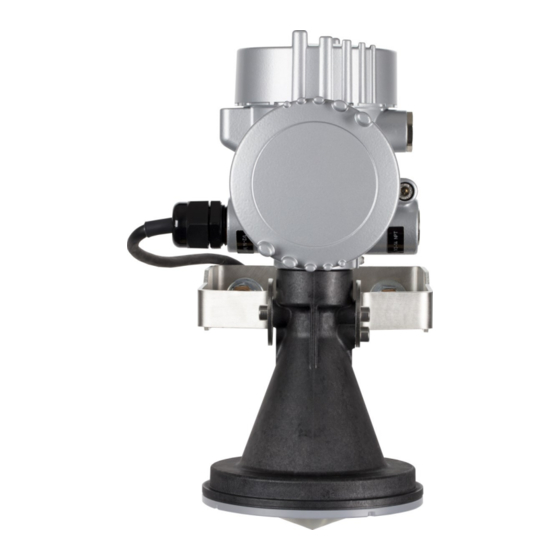
Page 10: Components And Hardware
5 Instrument horn FIGURE 5-2. Components and hardware 6. Specifications Measurement range: FIGURE 6-1 (p. 8) 0.5 to 35 m (1.64 to 114.8 ft); d in Accuracy: ±2 mm (±0.0065 ft) Resolution: 1 mm (0.0033 ft) CS475A Radar Water Level Sensor... -
Page 11: Radar Unit
FIGURE 6-1. Reference line for measurement range 6.1 Radar unit Frequency: ~26 GHz Pulse energy: 1 mW maximum Beam angle: 10° (3-inch diameter horn) Power requirements Input voltage: 9.6 to 32 VDC Surge protection: 1.5 kVA CS475A Radar Water Level Sensor... -
Page 12: Environmental
20 to 80% RH Vibration resistance: Mechanical vibrations with 4 g and 5 to 100 Hz 6.3 Physical FIGURE 6-2 (p. 10) for dimensions. Mechanical rating: IP66/68 Housing material: Aluminum Horn material: PVDF plastic Weight: 2 kg (4 lb) CS475A Radar Water Level Sensor... -
Page 13: Installation
(p. 11). Short Cut does this work for you. See QuickStart (p. 2) for a Short Cut tutorial. 7.1 Wiring to data logger Connections to Campbell Scientific data loggers are given in Table 7-1 (p. 11). CAUTION: Connect the wires in the order shown in Table 7-1 (p. -
Page 14: Built-In Self-Test (Bist)
For the CR6 and CR1000X Campbell Scientific data loggers, triggering conflicts may occur when a companion terminal is used for a triggering instruction such as TimerInput(), PulseCount(), or WaitDigTrig(). For example, if the CS475A is connected to C3 on a CR1000X, C4 cannot be used in the TimerInput(), PulseCount(), or WaitDigTrig() instructions. -
Page 15: Sdi-12 Programming
(p. 44). 7.2.1 SDI-12 programming SDI12Recorder() instruction is used to measure a CS475A configured for SDI-12 measurements. This instruction sends a request to the sensor to make a measurement and then retrieves the measurement from the sensor. See SDI-12 measurement commands (p. - Page 16 = clearance radius in the same measurement units as the CONE radius distance FIGURE 7-1. Beam path clearance CAUTION: Be aware that bridges contract and expand with temperature changes. Traffic loads or trucks can also cause changes to the bridge height. CS475A Radar Water Level Sensor...
- Page 17 To rotate the housing to the desired position: a. Loosen the set screw on the housing (FIGURE 7-3 (p. 15)). b. Rotate the housing as desired. c. Tighten the set screw. CS475A Radar Water Level Sensor...
- Page 18 The maximum range is reduced because of the off-axis return signal. To use the bubble level available from Campbell Scientific, do the following: a. Remove the top cap from the CS475A. b. Place the bubble level on the top of the CS475A (FIGURE 7-4 (p. 16)).
-
Page 19: Determine And Set Reference Stage
FIGURE 7-4. Campbell Scientific bubble level properly mounted on top of CS475A 5. Connect the sensor ground lug (FIGURE 7-3 (p. 15)) to a local earth ground using at least a 14 AWG wire. Connection to a local earth ground provides better surge or electrostatic discharge (ESD) protection than just grounding it via the sensor cable. -
Page 20: Operation
0 = feet Read/write Read only in DevConfig (must be set using terminal Stage reference emulation (Configuring sensor via extended SDI-12 commands and terminal emulator (p. 21)) Read/write though it can only Offset be written in SDI-12 CS475A Radar Water Level Sensor... -
Page 21: Configuring Sensor Using Device Configuration Utility
Configuration Utility CAUTION: Because the sensor board processor cannot speak HART when using the USB connection, the stage reference is set using the terminal emulator (Determine and set reference stage (p. 16)) during field installation. CS475A Radar Water Level Sensor... - Page 22 1. Open side compartment of the sensor by unscrewing the side cap (FIGURE 8-1 (p. 19)). FIGURE 8-1. CS475A with end cap and side cap in place (left). Exposed connectors once the side cap is removed (right). 2. Connect the USB cable to the USB port on the CS475A.
-
Page 23: Updating Operating System
5. If this is the first time connecting the CS475A to the computer, click Install USB Driver before connecting the cable to the computer. 6. Choose the Communication Port in which the CS475A is connected. Then click Connect. 7. Refer to the Device Configuration Utility Help section for any questions regarding the individual settings. -
Page 24: Configuring Sensor Via Extended Sdi-12 Commands And Terminal Emulator
5. Click the Send OS tab and follow the Operating System Download Instructions. 8.4 Configuring sensor via extended SDI-12 commands and terminal emulator The CS475A is fully configurable via SDI-12 extended commands through a terminal emulator program. The following instructions step you through the initial setup process. Table 8-2 (p. - Page 25 4. Press Enter until a prompt appears. 5. If using a Campbell Scientific data logger, type SDI12 <Enter> once the prompt is present. CS475A Radar Water Level Sensor...
- Page 26 Command: 0D0! Response: 0+50.000+0 The sensor response to the 0D0! command includes the sensor address (0) + reference stage (50.000) + error code (0). The CS475A error codes are explained in Table 9-1 (p. 42). CS475A Radar Water Level Sensor...
- Page 27 Command: 0A1! Response: 1 9. The default measurement units for the CS475A are English with stage and distance both being returned in feet. If you want the sensor to measure in metric units, you will need to change the units. Change the measurement units with aXWSU=1! (where feet = 0, meters = 1, and user defined = 2).
- Page 28 With the False Echo Suppression command, enter a distance that is 0.5 m (1.5 ft) short of the distance to the water surface, as measured in meters or feet, depending on the unit setting. CS475A Radar Water Level Sensor...
- Page 29 Range to 52 feet will eliminate false reading beyond this. Command: 0XXWMR=52.00! Response: 00022 Command: 0D0! Response: 0+52.00+0 The sensor response to the 0D0! command includes the sensor address (0) + new measuring range+ error code (0). CS475A Radar Water Level Sensor...
- Page 30 Table 8-2: Extended SDI-12 commands for the CS475A Command Sensor Command name Configuration by sensor format response Write SDI-12 aAb! Change the sensor address Address Returns the address of the sensor connected to the bus. This Read Sensor command is helpful when only...
- Page 31 Table 8-2: Extended SDI-12 commands for the CS475A Command Sensor Command name Configuration by sensor format response Change the slope. xxx.xxxx: new slope setting Write Slope aXWSS=xxx.xxxx atttn ee: error code Returns: New aD0! a+xxx.xxxx+ee To use this command, the System...
- Page 32 Table 8-2: Extended SDI-12 commands for the CS475A Command Sensor Command name Configuration by sensor format response Change the power mode of the sensor Write Power p: new current power mode Mode aXWPM=p! atttn setting, where: Returns: New a+p+ee aD0! 0 = low power mode;...
- Page 33 Table 8-2: Extended SDI-12 commands for the CS475A Command Sensor Command name Configuration by sensor format response Write Number of Measurements Change the number of for the M2! measurements completed for the Command M2! Response aXWNM2=nn! atttn Returns: New nnn: number of measurements...
- Page 34 Table 8-2: Extended SDI-12 commands for the CS475A Command Sensor Command name Configuration by sensor format response Read Number of Pull the number of measurements Measurements completed for the M3! Response for the M3! from memory aXRNM3! atttn Command nn: number of measurements...
- Page 35 Table 8-2: Extended SDI-12 commands for the CS475A Command Sensor Command name Configuration by sensor format response Pull the measuring range out of Read Measuring memory. Range aXRMR! atttn mmm.mm: current measuring Returns: aD0! a+mmm.mm+ee range Measuring range, error code...
- Page 36 Table 8-2: Extended SDI-12 commands for the CS475A Command Sensor Command name Configuration by sensor format response Read Falling Pull the falling amplitude Amplitude averaging factor (0-5) out of Averaging Factor memory aXRAS! atttn Returns: Falling z: current falling amplitude...
- Page 37 Table 8-2: Extended SDI-12 commands for the CS475A Command Sensor Command name Configuration by sensor format response Pull settings out of memory u: current units value out of memory (0 = ft; 1 = m, 2 = custom) ooo.oo: calculated offset out of...
- Page 38 Table 8-2: Extended SDI-12 commands for the CS475A Command Sensor Command name Configuration by sensor format response This command will put the sensor into a continuous output mode with data coming into the a++sss.ss+ terminal every second. Any other ddd.dd+...
- Page 39 Table 8-2: Extended SDI-12 commands for the CS475A Command Sensor Command name Configuration by sensor format response CS475A SDI-12 Command List: a! – Acknowledge Active aI! – Send Identification aAb! – Change Address aM! – Start Measurement aM1! – Start NOAA Measurement aM2! –...
-
Page 40: Sdi-12 Measurement Commands
8.5 SDI-12 measurement commands The data logger can send three categories of measurement commands to the CS475A using the SDI12Recorder() instruction. The two main categories of measurement commands are the Start Measurement (aMb!) and Start Concurrent Measurement (aCb!) commands. - Page 41 SDI-12 sensor address (default of 0). See Table 8-4 (p. 39) for the measurement commands recognized by the CS475A, the values returned with each command, and the response time of the sensor to each command. Table 8-3: Measurement examples...
- Page 42 Then once the aMC1! +oo+gg+vv.vv+ee buffers are full the sensor can aC1! return a 360 s average within 1 s. aCC1! Returns: mean stage, standard deviation, # of outliers, # of good readings, voltage, and error code CS475A Radar Water Level Sensor...
- Page 43 See extended SDI-12 commands to change the number of measurements averaged in the M1, M2, and M3 commands. The M2, C2, M3, C3 commands are commonly used in NOAA ports and tides applications for simple average stage values of the 1 second data. CS475A Radar Water Level Sensor...
-
Page 44: Diagnostics, Repair, And Maintenance
The cyclic redundancy check (CRC) is used to produce and send a small, fixed-size checksum of a larger block of data to the data logger. This checksum detects errors after transmission or storage. The CRC is computed and added before any transmission or storage. The CRC is also CS475A Radar Water Level Sensor... -
Page 45: Diagnostics
There was an error on the communication line. Check all of the Communication connections to make sure they are correct. Restart the system. If the Error problem persists, contact technical support. 9.4 Maintenance The CS475A is maintenance free under normal operation. CS475A Radar Water Level Sensor... - Page 46 Block. This adds an apostrophe (') to the beginning of each of the highlighted lines, which instructs the data logger compiler to ignore those lines when compiling. The Comment Block feature is demonstrated at about 5:10 in the CRBasic | Features video CS475A Radar Water Level Sensor...
- Page 47 Error_Code = NA 'unitless DataTable (CS475A,1,-1) Sample (4,CS475A(),FP2) EndTable BeginProg Scan (5,Sec,0,0) 'The sensor takes up to 1 s to respond to the M! command in normal power 'mode. SDI12Recorder "M!" (CS475A,C1,0, ,1.0,0,-1) CallTable CS475A NextScan EndProg CS475A Radar Water Level Sensor...
- Page 48 'Could be meters based on settings in sensor Units outliers = count Units good_meas = count Units Batt_volt_sensor = V Units Error_Code = NA 'unitless DataTable (CS475A,1,-1) Sample (6,CS475A(),FP2) EndTable BeginProg Scan (5,Sec,0,0) SDI12Recorder (CS475A,C1,0, "M1!" ,1.0,0,-1) CallTable CS475A NextScan EndProg CS475A Radar Water Level Sensor...
- Page 49 The specific identify parameter commands will return a SHEF code, the measurement units, and the type of measurement (sample, count, or average). For more information see the SDI-12 version 1.4 specification. (http://sdi-12.org/current_specification/SDI-12_version-1_4-Jan-10-2019.pdf) Table C-1: Identify commands for the CS475A Type of command Command Sensor response...
- Page 50 002! 002! FT=feet, M=meters aIM1_ aIC1_ a,bad,count,sample; # of Outliers 003! 003! aIM1_ aIC1_ # of Good a,good,count,sample; 004! 004! Values aIM1_ aIC1_ Battery a,vb,vdc,sample; 005! 005! Voltage aIM1_ aIC1_ a,error,code,sample; Error Code 006! 006! CS475A Radar Water Level Sensor...
- Page 51 Table C-5: Identify measurement parameters for M3! and C3! commands Commands Parameter Sensor response Comment xx: configured units Stage aIM3_001! aIC3_001! a,hg,xx,average; Average FT=feet, M=meters Battery aIM3_002! aIC3_002! a,vb,vdc,sample; Voltage aIM3_003! aIC3_003! a,error,code,sample; Error Code CS475A Radar Water Level Sensor...
- Page 52 (USA/Canada only) The CS475A is FCC compliant (FCC IC # M01PULS616263). Modifications to the sensor must have express agreement from Campbell Scientific. Any modifications not approved by Campbell Scientific will cause the expiration of the operating license issued by the FCC/IC. The radar sensor is in conformity with Part 15 of the FCC directives and fulfills the RSS-210 regulations.
- Page 53 See Product Details on the Ordering Information pages at www.campbellsci.com. Other manufacturer's products, that are resold by Campbell Scientific, are warranted only to the limits extended by the original manufacturer.
- Page 54 Campbell Scientific reserves the right to refuse service on products that were exposed to contaminants that may cause health or safety concerns for our employees.
- Page 55 Do not recharge, disassemble, heat above 100 °C (212 °F), solder directly to the cell, incinerate, or expose contents to water. Dispose of spent batteries properly. WHILE EVERY ATTEMPT IS MADE TO EMBODY THE HIGHEST DEGREE OF SAFETY IN ALL CAMPBELL SCIENTIFIC PRODUCTS, THE CUSTOMER ASSUMES ALL RISK FROM ANY INJURY RESULTING FROM IMPROPER INSTALLATION, USE, OR MAINTENANCE OF TRIPODS, TOWERS, OR...
- Page 56 Campbell Scientific regional offices Australia France Thailand Location: Garbutt, QLD Australia Location: Vincennes, France Location: Bangkok, Thailand Phone: 61.7.4401.7700 Phone: 0033.0.1.56.45.15.20 Phone: 66.2.719.3399 Email: info@campbellsci.com.au Email: info@campbellsci.fr Email: info@campbellsci.asia Website: www.campbellsci.com.au Website: www.campbellsci.fr Website: www.campbellsci.asia Brazil Germany Location: São Paulo, SP Brazil...
Need help?
Do you have a question about the CS475A and is the answer not in the manual?
Questions and answers