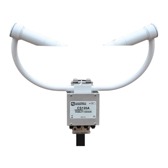
Campbell CS120A User Manual
Visibility sensor
Hide thumbs
Also See for CS120A:
- Instruction manual (94 pages) ,
- Product manual (77 pages) ,
- Installation manual (18 pages)

Related Manuals for Campbell CS120A


Summary of Contents for Campbell CS120A
- Page 1 CS120A Visibility Sensor Issued: 24.2.15 Copyright © 2014-2015 Campbell Scientific Ltd. CSL 1036...
- Page 3 Quotations for repairs can be given on request. It is the policy of Campbell Scientific to protect the health of its employees and provide a safe working environment, in support of this policy a “Declaration of Hazardous Material and Decontamination”...
- Page 5 Campbell Scientific Ltd can advise on the recycling of the equipment and in some cases arrange collection and the correct disposal of it, although charges may apply for some items or territories.
- Page 7 • Periodically (at least yearly) check electrical ground connections. WHILE EVERY ATTEMPT IS MADE TO EMBODY THE HIGHEST DEGREE OF SAFETY IN ALL CAMPBELL SCIENTIFIC PRODUCTS, THE CUSTOMER ASSUMES ALL RISK FROM ANY INJURY RESULTING FROM IMPROPER INSTALLATION, USE, OR MAINTENANCE OF TRIPODS, TOWERS, OR ATTACHMENTS TO TRIPODS AND TOWERS...
-
Page 9: Table Of Contents
10. Message Formats: A breakdown of the different default outputs of the CS120A – Basic/Partial/Full ........... 17 10.1 Example CS120A message outputs ............20 11. Interface methods – Device Configuration Utility/Command Line/Menu ......... 20 11.1 Configuring a PC for talking to the CS120A ........21... - Page 10 13.2 The SETNC Command ................ 26 13.2.1 Example of a SETNC Command ..........26 13.3 The GET command ................26 13.4 The POLL command – Polling the CS120A ........28 14. Entering the CS120A menu system ....... 29 15. Calibrating the CS120A .......... 32 16.
-
Page 11: Introduction
The CS120A is a development of the CS120. Functionally they are identical. The CS120A has a more powerful processor and can be upgraded to a CS125 with a present weather capability. This User Guide will be suitable for CS120s but note that CS120A operating systems cannot be loaded onto a CS120. -
Page 12: General Safety
These should be followed carefully in order to gain the maximum benefit from the use of this product. 1.3 Sensor Unit Safety The CS120A sensor has been checked for safety before leaving the factory and contains no internally replaceable or modifiable parts. WARNING Do not modify the CS120A unit. -
Page 13: Technical Specification
User Guide 2. Technical specification Minimum Nominal Maximum Value Value Value Visibility characteristics Reported Visibility (metric) 10 metres 32,000 metres Reported Visibility (imperial) 33 feet 104,985 feet Visibility accuracy up to 10,000 m +/-10% Visibility accuracy over 10,000 m +/-15% Visibility accuracy over 15,000 m +/-20% Optical characteristics... -
Page 14: Supported Data Rates For Rs232 And Rs485
(3) The ground of the CS120A and the ground of any RS485 equipment cannot be further apart than this voltage. The CS120A ground (pin 1 on connector B, see page 11) can be connected to the ground of the host equipment. This will reduce any parasitic currents. -
Page 15: Environmental Specifications
Hood heater Turn Off >15°C (1) Extended temperature ranges are only guaranteed if the sensor has been tested by Campbell Scientific and verified within this temperature range. Some degradation of absolute accuracy can be expected at the extremes of the extended ranges. - Page 16 (unless the analysis of microclimate weather is being sought). The CS120A has good resistance to background light but it is a good idea to avoid locations where the transmitter is pointing at a light scattering or reflecting surface.
-
Page 17: Equipment Grounding
Only tighten the nuts to a degree necessary to hold the CS120A firmly in place. Where the CS120A is to be mounted onto another type of mast, please refer to the manual for that mast for mounting details. -
Page 18: Optional Campbell Scientific Mount
Slots are provided to allow band clamps to be used with larger diameter masts. 7.3 Optional Campbell Scientific Mount A Campbell Scientific `optical sensor mount’, part number 009354, is available. This will put the sample volume at about 1.5 m in compliance with the WMO `Guide to Meteorological Instruments and Methods of Observation’, 7... - Page 19 User Guide If one is to be used, follow the installation instructions below. The mount should be installed on a concrete foundation. If one does not already exist then a concrete foundation should be constructed at least 600 mm square and 600 mm deep.
-
Page 20: Cs120A Internal Connectors' Description
8. CS120A internal connectors’ description The CS120A has three standard IP66 rated glands. The first gland is by default used by the power/communications line. This comprises the +12V/24V for the main electronics, and the serial communications wires. The CS120A is supplied with 5 m cable already connected. - Page 21 User Guide A configuration cable, part number 010817, is available from Campbell Scientific that plugs directly into connector B, in place of the normal connector and cable. The configuration cable is fitted with a 9-way D-connector for use with a PC serial port or USB to serial adaptor.
-
Page 22: Cs120A Recommended Wiring Using Campbell Scientific Cables
(this cable is supplied already connected as standard) The CS120A is provided pre-wired with a default 5 m power and communications cable which is terminated at one end with a 9 pin D-connector (DB9). The D-connector can be connected directly to a PC or to a datalogger such as the Campbell Scientific CR1000 using a suitable interconnecting cable such as the SC110. - Page 23 User Guide...
- Page 24 CS120A Visibility Sensor...
- Page 25 User Guide...
-
Page 26: Functions Of The Internal Switches
‘Save and exit’ command is performed these new data rate settings will be committed to flash. Once this switch is returned to its OFF position and the CS120A is power cycled the CS120A will return to its previous communications... -
Page 27: Message Formats: A Breakdown Of The Different Default Outputs Of The Cs120A - Basic/Partial/Full
User Guide Reserved for future use, set to OFF. When switched to the ON position this switch will reset the CS120A to its factory default values. This reset will affect all communication setting and will replace the user calibration settings with the factory defaults. - Page 28 CS120A Visibility Sensor Full format 0 0 0… 0x02 M or F XXXX 0x03 0x0D 0x0A Message ID break down Definition Basic format. Contains only distance and system information Partial format. Contains user alarm outputs Full format. Contains all system alarms codes...
- Page 29 One minute average Ten minute average In accordance with WMO requirements the CS120A produces measurement that are either one or ten minute rolling averages that are updated at the chosen output interval or when the sensor is polled. Those averages are not direct averages of MOR measurements but are averages of extinction coefficient and that average is then used to calculate the MOR for that period.
-
Page 30: Example Cs120A Message Outputs
1 = One or more errors writing user variables to flash occurred The emitter power level reporting too high will cause the CS120A to shutdown and go into low power mode. The severity of the alarm. The higher the number the more serious the error is considered to be. -
Page 31: Configuring A Pc For Talking To The Cs120A
CS120A and to access its calibration menu. Note that the CS120A is listed on DevConfig as a different sensor to the CS120. If only the CS120 is listed then you should update your version of Devconfig. This is available free on the Campbell Scientific website. -
Page 32: Definition Of The Variables That Can Be Set By The User On The Cs120A
12. Definition of the variables that can be set by the user on the CS120A Both DevConfig and the command line interface can access all the user configurable variables within the CS120A. The acceptable range and the identification number for these variables are listed below along with a short description. -
Page 33: Command Line Mode
GET, SET and POLL. The GET command is used to request all current user settable values from the CS120A. The SET commands sets user settable values and the POLL command is used to request the current visibility and/or alarm... -
Page 34: The Set Command
CS120A Visibility Sensor The CS120A can be configured to expect any commands sent to it to include a valid checksum. For simple commands, e.g. GET and POLL, fixed value checksums can be used (see the example programs). For more complex SET commands the checksum needs to be calculated (see Appendix B). -
Page 35: Example Of A Set Command
User Guide SET transmitted data Example Description 0x02 STX ^B Delimiting character Delimiting character Address based on Sensor ID Delimiting character Sensor ID User Alarm 1 Set User Alarm 1 Active User Alarm 1 Distance User Alarm 2 Set User Alarm 2 Active User Alarm 2 Distance Serial Baud Rate Sensor serial number (read only) -
Page 36: The Setnc Command
This means that the next time the CS120A is power cycled it will revert back to its previous settings. This command should be used when a setting in the sensor is changed regularly, e.g. heater functions, as this command avoids the risk of wearing out the flash storage memory. - Page 37 User Guide Example data returned by the GET command – See Section 12 for more information on values returned by the `GET’ command GET returned data Example Description 0x02 Sensor ID User Alarm 1 Set User Alarm 1 Active User Alarm 1 Distance User Alarm 2 Set User Alarm 2 Active User Alarm 2 Distance...
-
Page 38: The Poll Command - Polling The Cs120A
13.4 The POLL command – Polling the CS120A The POLL command requests the current visibility and/or alarm conditions from the CS120A. The output format of this command depends on how the CS120A is configured using the SET command or the menu interfaces. -
Page 39: Entering The Cs120A Menu System
No changes will take effect until you `Exit and Save’. The exception to this is the calibration menu, but you will be informed before any changes are made. Typing `1’ opens the message menu containing settings relating to the CS120A’s outputs. - Page 40 CS120A Visibility Sensor Menu 1: The message output menu CS120A MESSAGE - MENU 1 ID 0 S/N 1009 (1) Toggle message format:FULL (2) Toggle units:METRES (3) Toggle polled or continuous mode:CONTINUOUS (4) Set continuous mode output interval:6 second(s) (5) Toggle output averaging period: 1 minute(s)
- Page 41 The disk constants however remain as the last disk used. Option (4) gives the systems information menu containing useful information such as temperature and system alarms. Menu 4: The system information menu CS120A INFORMATION - MENU 4 ID 0 S/N 1009 OS version: CS120Av7 Alarm...
-
Page 42: Calibrating The Cs120A
010815. The calibration must be run using the onboard menu system. If you have Campbell Scientific’s Device configuration program a terminal emulation screen is provided in the CS120A screens to let you access this function. To perform the calibration you will need a CS120A calibrator disk and a computer with a standard serial port compatible with the CS120A. - Page 43 Do you want to perform a calibration Y/N? Once you have started the tests you will be asked for the CS120A calibrator serial number and coefficient with a confirmation at each step giving you the chance to correct typing mistakes.
- Page 44 CS120A Visibility Sensor When you have entered the calibrator information the sensor will wait for you to place the foam bungs into the sensor hoods. The bungs are designed to block all light from the outside reaching inside the head. Place one bung into each hood. If either of the bungs are damaged or appear to have any gaps around the edge please contact Campbell Scientific.
- Page 45 Now place the CS120A calibrator into the sampling volume. Press any key once this is done. Remove the bungs once the sensor instructs you to. Place the CS120A calibrator into the volume by fastening it to the central mounting point. NOTE At this stage it is advisable to clean the lenses.
-
Page 46: Performing An Operating System Update
Campbell Scientific if required. Only general cleaning of the lenses is required to keep the sensor working efficiently. Cleaning of the CS120A will be required from time to time to ensure that the lenses are free from contaminants. The frequency of required cleaning depends on the exposure of the instrument to such contaminants. -
Page 47: Lubricating The Enclosure Screws
18. Lubricating the enclosure screws The CS120A enclosure screws should be lubricated with a suitable anti-seize grease (often copper loaded) to protect the threads from corrosion. This should be reapplied when resealing the enclosure at regular intervals, normally after replacing the desiccant. - Page 48 CS120A Visibility Sensor Set the temperature of the oven to 118°C, and allow the bags of desiccant to reach equilibrium temperature. Tyvek has a melting temperature of 121°C - 127°C. CAUTION (NON MIL-D-3464E activation or reactivation of both silica gel and Bentonite clay can be achieved at temperatures of 104°C).
-
Page 49: Cs120A Block Diagram
Appendix A. CS120A block diagram Detector hood Emitter hood Transimpedance Photo- Power level + 850nm amplifier detector Driver circuitry Emitter Emitter power Amplifier Amplifier feedback and filter and filter Dirty window Dirty window detector detector Hood temperature Hood heater Hood heater... - Page 50 CS120A Visibility Sensor...
-
Page 51: Example C Code Of The Ccitt Crc
Appendix B. Example C code of the CCITT The code below is provided as an example for programmers implementing their own code to communicate with the sensor. Users using Campbell loggers can use the Checksum command in CRBasic to generate a CCITT checksum. Command: Checksum/ChkSumString,1,0). - Page 52 CS120A Visibility Sensor...
-
Page 53: Example Crbasic Programs
Alias SerialIndest(18)=Flash_read_error '0..1 - Flash Read Error Alias SerialIndest(19)=Flash_write_error '0..1 - Flash Write Error Alias SerialIndest(20) = checksumrx 'CCITT Checksum 'Define the serial port to which the CS120A is connected - amend as needed Const CS120A_Comport = COM1 'Main Program... - Page 54 Alias SerialIndest(19)=Flash_write_error '0..1 - Flash Write Error Alias SerialIndest(20) = checksumrx 'CCITT Checksum 'Define the serial port to which the CS120A is connected - amend as needed Const CS120A_Comport = COM1 'Preload the poll command for a sensor for address 0, in this example 'If the sensor has a different address uncomment the relevant line Const CS120A_Poll = CHR(2)&"POLL:0:0:3A3B:"&CHR(3)&CHR(13) 'address 0...
- Page 55 Appendix C. Example CRBasic programs 'Extract the checksum from the message & convert it for comparison lngCRCMsg = HexToDec(checksumrx) ChecksumOK = ( lngCRCMsg = lngCRCCalc) 'In critical applications the visibility can be set to NaN if the system status 'is degraded or a critical error flag is set. If ChecksumOK Then Visibility = Visibilitystr Else Visibility =NaN EndIf 'Call data storage commands here...
- Page 56 '------------------------------------------------------------------------------- ' CS120A Visibility ' Program to test the SET command part of the command line interface on the CS120A ' Do not run this script for extended periods of time (days!) as it writes ' to flash over and over and will eventually wear the flash out...
- Page 57 Appendix C. Example CRBasic programs CheckVal = CheckSum (TempStringFunc,1,0) ' Use the CCITT CRC16 checksum ' Create final string going out to CS120A including start characters and end characters CS120ACommandString = CHR(2) + TempStringFunc + ":" + FormatLong (CheckVal,"%04X") + ":" + CHR(3) + CHR(13) + CHR(10)
- Page 58 Public InStringSETNC As String * 200 Public InStringGET As String * 200 Public TRHData(2) Public OutString As String * 40, CheckVal Dim CS120ACArray(21) As String * 6 ' CS120A Command Array Dim TempDewPoint Dim StatusDewHeater Dim TempString As String * 100...
- Page 59 ' Create a check sum of the values going out CheckVal = CheckSum (TempStringFunc,1,0) ' Use the CCITT CRC16 checksum ' Create final string going out to CS120A including start characters and end characters CS120ACommandString = CHR(2) + TempStringFunc + ":" + FormatLong (CheckVal,"%04X") + ":"...
- Page 60 Scan (10,Sec,0,0) 'CS215 Temperature & Relative Humidity Sensor measurements AirTC and RH SDI12Recorder(TRHData(),5,"0","M!",1,0) 'Calculate DewPoint DewPoint(TempDewPoint,AirTC,RH) ' Gather the current settings from the CS120A SerialFlush (Com1) TempString = "GET:0:0" CheckVal = CheckSum (TempString,1,0) ' Use the CCITT CRC16 checksum OutString = CHR(2) + TempString + ":" + FormatLong (CheckVal,"%04X") + ":" + CHR(3) + CHR(13) + CHR(10) SerialOut (Com1,OutString,"",0,100)
- Page 61 C.5 Example CRBasic GET program '------------------------------------------------------------------------------- ' CS120A Visibility ' Program to test the GET command part of the command line interface on the CS120A ' Connecting to serial port one on a CR1000 logger ' Logger:CR1000 ' Example outputs including checksums (varies with sensor ID)
- Page 62 CAMPBELL SCIENTIFIC COMPANIES Campbell Scientific, Inc. (CSI) 815 West 1800 North Logan, Utah 84321 UNITED STATES www.campbellsci.com info@campbellsci.com Campbell Scientific Africa Pty. Ltd. (CSAf) PO Box 2450 Somerset West 7129 SOUTH AFRICA www.csafrica.co.za sales@csafrica.co.za Campbell Scientific Australia Pty. Ltd. (CSA)
Need help?
Do you have a question about the CS120A and is the answer not in the manual?
Questions and answers