
Subscribe to Our Youtube Channel
Related Manuals for Campbell CS475


Summary of Contents for Campbell CS475
- Page 1 CS475, CS476, and CS477 Radar Water Level Sensors Revision: 5/17 C o p y r i g h t © 2 0 0 9 - 2 0 1 7 C a m p b e l l S c i e n t i f i c ,...
- Page 3 Limited Warranty “Products manufactured by CSI are warranted by CSI to be free from defects in materials and workmanship under normal use and service for twelve months from the date of shipment unless otherwise specified in the corresponding product manual. (Product manuals are available for review online at www.campbellsci.com.) Products not manufactured by CSI, but that are resold by CSI, are warranted only to the limits extended by the original manufacturer.
- Page 4 Campbell Scientific company serves your country. To obtain a Returned Materials Authorization (RMA) number, contact CAMPBELL SCIENTIFIC, INC., phone (435) 227-9000. Please write the issued RMA number clearly on the outside of the shipping container. Campbell Scientific’s shipping address is: CAMPBELL SCIENTIFIC, INC.
- Page 5 Periodically (at least yearly) check electrical ground connections. • WHILE EVERY ATTEMPT IS MADE TO EMBODY THE HIGHEST DEGREE OF SAFETY IN ALL CAMPBELL SCIENTIFIC PRODUCTS, THE CUSTOMER ASSUMES ALL RISK FROM ANY INJURY RESULTING FROM IMPROPER INSTALLATION, USE, OR MAINTENANCE OF TRIPODS, TOWERS, OR ATTACHMENTS TO TRIPODS AND TOWERS SUCH AS SENSORS, CROSSARMS, ENCLOSURES, ANTENNAS, ETC.
-
Page 7: Table Of Contents
Table of Contents PDF viewers: These page numbers refer to the printed version of this document. Use the PDF reader bookmarks tab for links to specific sections. 1. Introduction ..............1 2. Precautions ..............1 3. Initial Inspection ............2 4. - Page 8 Tables 5-1. Description of Components and Hardware Labels ......6 7-1. Radiation Beam Spread for CS475 (10° Beam Angle) ..... 12 7-2. Radiation Beam Spread for CS476/CS477 (8° Beam Angle) ... 12 7-3. Description of Polarization Markings Labels ........13 7-4.
- Page 9 Table of Contents C-9. Acknowledge Active Command ............C-7 C-10. Send Identification Command............C-8 C-11. Checking CRC Example ..............C-9 CRBasic Example B-1. CR1000 Program Measuring the CS475 .......... B-1...
- Page 10 Table of Contents...
-
Page 11: Introduction
• Care should be taken when opening the shipping package to not damage or cut the cable jacket. If damage to the cable is suspected, contact Campbell Scientific. Handle the sensor carefully, since it is a precision instrument. •... -
Page 12: Initial Inspection
CS475, CS476, and CS477 Radar Water Level Sensor Initial Inspection When unpacking the equipment, do the following: Unpack the unit in a clean, dry area. • • Inspect the equipment for any damage that occurred during shipping or storage. If the equipment is damaged, file a claim against the carrier and report •... - Page 13 Select Datalogger Model and Scan Interval (default of 10 seconds is OK for most applications). Click Next. Under the Available Sensors and Devices list, select the Sensors | Water | Level & Flow folder. Select CS475/CS476/CS477 Radar Water Level Sensor, click to move the selection to the Selected device window.
-
Page 14: Overview
Three sensor models are available that differ in their measurement range and accuracy (FIGURE 5-1). The CS475 can measure distances up to 65 feet with an accuracy of ±0.2 inches; the CS476 can measure up to 98 feet with an accuracy of ±0.1 inches;... -
Page 15: Components And Hardware
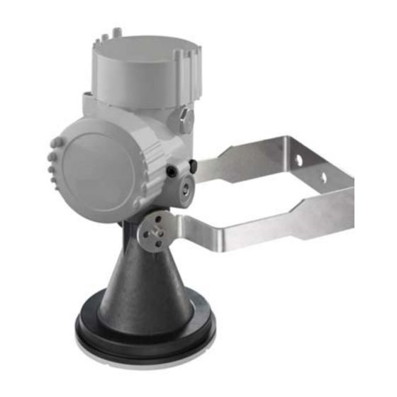
CS475, CS476, and CS477 Radar Water Level Sensor FIGURE 5-1. CS475, CS476, and CS477 Components and Hardware The radar sensor consists of an integrated microwave transmitter and sensor together with a horn antenna (see FIGURE and TABLE 5-1). The horn antenna serves to focus the transmitted signal and to receive the reflected echo. -
Page 16: Components And Hardware (See Table 5-1 For Description Of Labels)
CS475, CS476, and CS477 Radar Water Level Sensor FIGURE 5-2. Components and hardware (see TABLE description of labels) TABLE 5-1. Description of Components and Hardware Labels CS475 CS476 or CS477 Mounting Loop PULS Housing Side Cap PULS Housing Cap PULS Unit Secondary 1/2” NPT Cable Port, Primary Port on... -
Page 17: Specifications
CS475, CS476, and CS477 Radar Water Level Sensor Specifications Features: • FCC compliant • Ideal for areas where submersed sensors can be damaged due to corrosion, contamination, flood-related debris, lightning, or vandalism Low maintenance—no moving parts significantly reduces • maintenance cost and time Low power consumption •... -
Page 18: Radar Unit
CS475, CS476, and CS477 Radar Water Level Sensor Radar Unit Frequency: ~26 GHz Electromagnetic Compatibility: Emission to EN 61326; Electrical Equipment Class B Pulse Energy: 1 mW maximum Beam Angle CS475: 10° (3-in dia horn) CS476, CS477: 8° (4-in dia horn) -
Page 19: Cs475 Dimensions
CS475, CS476, and CS477 Radar Water Level Sensor 86 mm (3.4 in) 129 mm (5.1 in) 86 mm (3.4 in) 122 mm (4.8 in) 15 mm (0.6 in) 75 mm (3 in) 115 mm (4.5 in) FIGURE 6-2. CS475 dimensions... -
Page 20: Cs476/Cs477 Dimensions
CS475, CS476, and CS477 Radar Water Level Sensor 86 mm (3.4 in) 86 mm (3.4 in) 585 mm (23 in) 430 mm (16.9 in) 95 mm (3.7 in) FIGURE 6-3. CS476/CS477 dimensions... -
Page 21: Installation
The radiation beam spreads as it leaves the sensor (see TABLE and TABLE 7-2). Usually the beam path is 10° for the CS475, and 8° for the NOTE CS476/CS477. Be aware that bridges contract and expand with temperature changes. -
Page 22: Radiation Beam Spread For Cs475 (10° Beam Angle)
The radiation beam spreads as it leaves the sensor (see TABLE and TABLE 7-2). Usually the beam path is 10° for the CS475, and 8° for the NOTE CS476/CS477. TABLE 7-1. Radiation Beam Spread for CS475 (10°... -
Page 23: Description Of Polarization Markings Labels
CS475, CS476, and CS477 Radar Water Level Sensor CS475 CS476/CS477 FIGURE 7-1. Polarization markings (see TABLE for label descriptions) TABLE 7-3. Description of Polarization Markings Labels Sensor Description CS475 Polarization marks are designated by the mounting loop screws. CS476/CS477 Polarization mark is machine-tooled. -
Page 24: Wiring To Datalogger
CS475, CS476, and CS477 Radar Water Level Sensor Wiring to Datalogger Connections to Campbell Scientific dataloggers are given in TABLE 7-4. CAUTION Connect the wires in the order shown in TABLE 7-4. TABLE 7-4. Wire Color, Function, and Datalogger Connection... -
Page 25: Sdi12Recorder() Instruction
CS475, CS476, and CS477 Radar Water Level Sensor CRBasic Editor . Programming basics for CRBasic dataloggers are (p. A-1) provided in the following sections. A complete program example can be found in Appendix B, Example Program (p. B-1) 7.4.1 SDI12Recorder() Instruction Use the SDI12Recorder() measurement instruction to program the datalogger to measure the sensor. -
Page 26: Sensor Measurement
CS475, CS476, and CS477 Radar Water Level Sensor The 25616, Adjustment/Display Module, or the terminal emulator in LoggerNet or PC400 can be used to enter SDI-12 commands. Appendix C.2, Using Terminal Emulator and a Datalogger to Send Commands , describes (p. -
Page 27: Cyclic Redundancy Check
CS475, CS476, and CS477 Radar Water Level Sensor The test procedures for the sensor require the following steps: Double check all wiring connections. Connect the sensor to your datalogger and apply +12V power. Compare the Output Stage versus the Actual Stage using the Start Measurement command (aM!) followed by the Send Data command (aD!). -
Page 28: No Measured Value Available - Error E013
(p. 18) Return the equipment for repair • 9.3.2.1 Exchange Electronics Module If you do not have an electronics module onsite, order one from Campbell Scientific. The electronics module is replaced by doing the following steps (see FIGURE and TABLE 9-1): Unscrew the housing cap (cap is not shown in FIGURE 9-1). - Page 29 CS475, CS476, and CS477 Radar Water Level Sensor Loosen the two screws securing the electronics to the housing (3 in FIGURE 9-1). These screws are captive screws and will remain nested with the electronics. Gently remove the electronics from the housing (4 in FIGURE 9-1).
-
Page 30: Maintenance
CS475, CS476, and CS477 Radar Water Level Sensor FIGURE 9-1. Changing the electronics (see TABLE for label descriptions) TABLE 9-1. Description of Changing the Electronics Labels Description Red Wire Housing Top View Screws to Secure Electronics to Housing Electronics Housing Side View Maintenance The sensors are maintenance free under normal operation. -
Page 31: Importing Short Cut Code Into Crbasic Editor
Appendix A. Importing Short Cut Code Into CRBasic Editor This tutorial shows: How to import a Short Cut program into a program editor for • additional refinement • How to import a wiring diagram from Short Cut into the comments of a custom program Short Cut creates files, which can be imported into CRBasic Editor. -
Page 33: Example Program
Appendix B. Example Program CRBasic Example B-1. CR1000 Program Measuring the CS475 'CR1000 Series Datalogger 'Declare the variable for the water level measurement Public CS475(3) 'Rename the variable names Alias CS475(1)=Stage Alias CS475(2)=Distance Alias CS475(3)=Error_Code 'Define a data table for 60 minute maximum and minimums... -
Page 35: Sdi-12 Commands/ Changing Settings
Appendix C. SDI-12 Commands/ Changing Settings The SDI-12 commands are entered using the 25616, Adjustment/Display Module, or the terminal emulator in LoggerNet or PC400 (see Appendix C.2, Using Terminal Emulator and a Datalogger to Send Commands ). These (p. C-9) commands are also used in CRBasic or Edlog programming (see Section 7.4, Datalogger Programming (p. -
Page 36: Query/Set The Address
Appendix C. SDI-12 Commands/ Changing Settings Start Concurrent Measurement aCC! and Request CRC Additional Concurrent aC1!...aC9! Measurements Additional Concurrent aCC1!...aCC9! Measurements and Request CRC Start False Echo Learn aXSFEL+n.nnn! n = distance necessary to clear the obstruction Set Power n Operation Mode aXSPOM+n! n = 2 (auto), 1 (on), or 0 (off) Get Power Operation Mode... -
Page 37: Set Water Stage
Appendix C. SDI-12 Commands/ Changing Settings Change the sensor’s address by sending the sensor the aAb! command, where “a” is the original address and “b” is the new address. TABLE shows an example of the command and response for setting the address. TABLE C-3. -
Page 38: Set Units
Appendix C. SDI-12 Commands/ Changing Settings radar sensor then emits the short microwave pulses. Any echo occurring 0.5 m (1.6 ft) short of the distance you entered will be considered noise. To start False Echo Learn, do the aXSFEL+nnn.nnn! command (where nnn.nnn = the actual distance to the water) followed by the aD0! (Send Data) command. -
Page 39: Set Water Conditions
Appendix C. SDI-12 Commands/ Changing Settings Initial Command Response 0XGU! 00011<cr><If> Where zero is the sensor address. Where (from left to right), This is the get units command 0—sensor’s address; 001—the amount of time (in seconds) that you must wait before sending another command;... -
Page 40: Set Power Operation Mode
Appendix C. SDI-12 Commands/ Changing Settings Subsequent Command Response 0D0! 0+2<cr><If> Where the first zero is the sensor’s Where, address. 0—sensor’s address; 2—the new water condition setting (2 = medium). Initial Command Response 0XGWC! 00011<cr><If> Where zero is the sensor address. Where (from left to right), This is the send water conditions 0—sensor’s address;... -
Page 41: Acknowledge Active Command
Appendix C. SDI-12 Commands/ Changing Settings TABLE C-8. Example for Setting and Getting Power Operation Mode Initial Command Response 0XSPOM+2! 00011<cr><If> Where, Where (from left to right), 0—sensor’s address; 0—sensor’s address; 2—the new power mode setting 001—the amount of time (in (2 = auto). -
Page 42: Send Identification Command
• Compatibility level: Version of SDI-12 protocol version; for example, 1.3. Manufacturer’s Name: VEGA • • Manufacturer’s Model Number: PS61 (CS475), PS62 (CS476), or PS63 (CS477) Three Digit Firmware Version Number. • Eight Digit Serial Number of Sensor. • TABLE C-10. Send Identification Command... -
Page 43: Using Terminal Emulator And A Datalogger To Send Commands
Transparent mode is entered while the PC is in telecommunications with the datalogger through a terminal emulator program. It is easily accessed through Campbell Scientific datalogger support software, but is also accessible with terminal emulator programs such as Windows HyperTerminal. Datalogger keyboards and displays cannot be used. -
Page 44: Sdi-12 Transparent Mode
Appendix C. SDI-12 Commands/ Changing Settings C.2.2 CR200(X) Series Datalogger Example Connect a single sensor to the datalogger as follows: White to Control Port C1/SDI12 • • Black, Clear to G Red to Battery + • In the LoggerNet Connect screen navigate to the Datalogger menu and select Terminal Emulator. -
Page 45: Cr1000 Datalogger Example
Appendix C. SDI-12 Commands/ Changing Settings C.2.3 CR1000 Datalogger Example Connect a single sensor to the datalogger as follows: White to Control Port C1 • • Black, Clear to G Red to 12V • In the LoggerNet Connect screen navigate to the Datalogger menu and select Terminal Emulator. - Page 46 Appendix C. SDI-12 Commands/ Changing Settings C-12...
-
Page 47: Fcc/Ic Equipment Authorization (Usa/Canada Only
Appendix D. FCC/IC Equipment Authorization (USA/Canada only) The CS475, CS476, and CS477 are FCC compliant (FCC IC # M01PULS616263). Modifications to the sensors must have express agreement from Campbell Scientific. Any modifications not approved by Campbell Scientific will cause the expiration of the operating license issued by the FCC/IC. - Page 50 Santo Domingo, Heredia 40305 SOUTH AFRICA COSTA RICA • cleroux@csafrica.co.za • info@campbellsci.cc www.campbellsci.co.za www.campbellsci.cc Campbell Scientific Southeast Asia Co., Ltd. Campbell Scientific Ltd. 877/22 Nirvana@Work, Rama 9 Road Campbell Park Suan Luang Subdistrict, Suan Luang District 80 Hathern Road Bangkok 10250...
Need help?
Do you have a question about the CS475 and is the answer not in the manual?
Questions and answers