Table of Contents
Advertisement
Quick Links
Advertisement
Table of Contents

Related Manuals for Gefen EXT-VGARS232-141


Summary of Contents for Gefen EXT-VGARS232-141
- Page 1 VGA RS232 Extender EXT-VGARS232-141 User Manual www.gefen.com...
- Page 2 Notice Gefen LLC reserves the right to make changes in the hard ware, packaging and any accompanying doc u men ta tion without prior written notice. VGA RS232 Extender is a trademark of Gefen, LLC © 2011 Gefen LLC. All rights reserved.
-
Page 3: Table Of Contents
CONTENTS Introduction Operation Notes Features Sender Unit Layout Sender Unit Descriptions Receiver Unit Layout Receiver Unit Descriptions Connecting and Operating the VGA RS232 Extender How to Connect the VGA RS232 Extender Wiring Diagram Brightness Control Cable Skew / Color Divergence Control 12 RS-232 Serial Control 13 Network Cable Wiring Diagram 14 Wall Mounting Instructions... -
Page 4: Introduction
Standard Time for assistance with your A/V needs. We’ll be happy to assist you. The Gefen VGA RS232 Extender The Gefen VGA RS232 extends any VGA source to a monitor or digital signage application placed up to 330 feet (100 meters) using one CAT-5 cable. This product also extends RS-232 using the same CAT-5 cable, allowing access to control devices using RS-232. -
Page 5: Operation Notes
OPERATION NOTES READ THESE NOTES BEFORE INSTALLING OR OPERATING THE GEFEN VGA RS232 EXTENDER • CAT-5e cables should not exceed 330 feet (100 meters). • Unshielded (UTP) CAT-5e is recommended. -
Page 6: Features
All-digital signal transmission for zero signal loss • Metal enclosure improves RF shielding Package Includes (1) Gefen VGA RS232 Extender Sender Unit (1) Gefen VGA RS232 Extender Receiver Unit (1) 6 ft. VGA cable (M-F) (1) 6 ft. serial cable (M-F) -
Page 7: Sender Unit Layout
SENDER UNIT LAYOUT Front Back... -
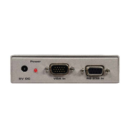
Page 8: Sender Unit Descriptions
SENDER UNIT DESCRIPTIONS 5V DC Power Connector Connect the included 5V DC power supply to this connector. Power Indicator This LED will turn bright red once the included 5V DC power supply has been properly connected to the unit and the power supply has been connected to an available electrical outlet. -
Page 9: Receiver Unit Layout
RECEIVER UNIT LAYOUT Front Back... -
Page 10: Receiver Unit Descriptions
RECEIVER UNIT DESCRIPTIONS Locking VGA Port Connect a VGA source device to this VGA port. RS-232 Port Connect the RS-232 device to this port. Brightness Trimpot Adjusts the brightness of the picture. Power Indicator This LED will turn bright red once the included 5V DC power supply has been properly connected to the unit and the locking power supply has been connected to an available electrical outlet. -
Page 11: Connecting And Operating The Vga Rs232 Extender
CONNECTING AND OPERATING THE GEFEN VGA RS232 EXTENDER How to Connect the VGA RS232 Extender Connect the VGA source to the Sender Unit using the provided VGA cable. Connect the VGA monitor to the Receiver Unit using a VGA cable. -
Page 12: Brightness Control
CONNECTING AND OPERATING THE GEFEN VGA RS232 EXTENDER Brightness Control The VGA RS232 Extender Receiver Unit has a brightness trimpot to adjust the brightness of the picture. If the picture appears too dark or too bright, following the instructions below. -
Page 13: Cable Skew / Color Divergence Control
CONNECTING AND OPERATING THE GEFEN VGA RS232 EXTENDER Cable Skew and Color Divergence Control To reduce the amount of crosstalk between twisted pairs within a CAT-5 cable, the rate of twist varies for each twisted pair. The rate of twist affects the length of each twisted pair and is referred to as cable skew. - Page 14 CONNECTING AND OPERATING THE GEFEN VGA RS232 EXTENDER The VGA RS232 Extender allows for compensation of cable skew using three (3) DIP switch banks, located on the bottom of the Receiver Unit. To access the DIP switches, peel back the small strip of silver-grey tape. Each DIP switch bank controls a different color component: Red, Green, and Blue.
-
Page 15: Rs-232 Serial Control
RS-232 SERIAL CONTROL This feature allows for easy integration into automated systems capable of transmitting RS-232 commands. The max allowable bit rate is 115,200 bps. -
Page 16: Network Cable Wiring Diagram
NETWORK CABLE WIRING DIAGRAM Gefen recommends the TIA/EIA-568-B wiring option. Please adhere to the table below when fi eld-terminating the CAT-5 cable for use with Gefen products. Color Orange / White Orange Green / White Blue Blue / White Green... -
Page 17: Wall Mounting Instructions
WALL MOUNTING INSTRUCTIONS... -
Page 18: Specifications
SPECIFICATIONS Video Amplifi er Bandwidth ............... 350 MHz Actual Bandwidth ..................120 MHz Input Video Signal ..................1.2 Vp-p Horizontal Frequency Range ..............15-70 KHz Vertical Frequency Range ..............30-170 Hz Video In ....................HD-15 Male Video Out ..................HD-15 Female Serial In (RS232 Connector) ............DB9 9-Pin Female Serial Out (RS232 Connector)............DB9 9-Pin Male Link Connector ..................... - Page 21 Rev A2 20600 Nordhoff St., Chatsworth CA 91311 1-800-545-6900 818-772-9100 fax: 818-772-9120 www.gefen.com support@gefen.com This product uses UL listed power supplies.
Need help?
Do you have a question about the EXT-VGARS232-141 and is the answer not in the manual?
Questions and answers