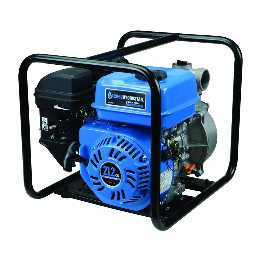
Pacific hydrostar 212cc Gasoline Powered Clear Water Pump Manual
212cc gasoline powered clear water pump
Hide thumbs
Also See for Pacific Hydrostar 212cc Gasoline Powered Clear Water Pump:
- Owner's manual & safety instructions (32 pages)
Table of Contents
Advertisement
Advertisement
Table of Contents
Troubleshooting

Related Manuals for Pacific hydrostar Pacific Hydrostar 212cc Gasoline Powered Clear Water Pump


Summary of Contents for Pacific hydrostar Pacific Hydrostar 212cc Gasoline Powered Clear Water Pump
-
Page 2: Table Of Contents
Table of Contents Specifications ..........2 Maintenance ..........13 Safety ............4 Troubleshooting ......... 17 Setup ............6 Warranties ..........20 Operation ........... 10 Parts Lists and Diagrams ......22 Specifications Pump Suction & Discharge Size 2" NPT Discharge Capacity 151 GPM Maximum Discharge Head 97.5 ft. - Page 3 WARNING SYMBOLS AND DEFINITIONS This is the safety alert symbol. It is used to alert you to potential personal injury hazards. Obey all safety messages that follow this symbol to avoid possible injury or death. Indicates a hazardous situation which, if not avoided, will result in death or serious injury.
-
Page 4: Safety
10. Use only accessories that are recommended Only use OUTSIDE and far away from windows, by Harbor Freight Tools for your model. doors, and vents. Accessories that may be suitable for one piece of equipment may become hazardous 2. -
Page 5: Save These Instructions
5. Wipe up any spilled fuel and allow excess If unreadable or missing, contact to evaporate before starting engine. Harbor Freight Tools for a replacement. To prevent FIRE, do not start the engine while the smell of fuel hangs in the air. -
Page 6: Setup
Set Up Read the ENTIRE IMPORTANT SAFETY INFORMATION section at the beginning of this manual including all text under subheadings therein before set up or use of this product. At high altitudes, the engine’s carburetor, governor (if so equipped), and any other parts that control the fuel‑air ratio will need to be adjusted by a TO PREVENT SERIOUS INJURY: qualified mechanic to allow efficient high‑altitude... - Page 7 Connecting Hoses Note: Hose coupling components 3. Slide one of the Hose Clamps over the end of the and hoses not included. suction hose (a). Slide the Hose onto the Hose Coupler (b). Use a screwdriver (not included) Note: The Suction Hose (not included) MUST to tighten the Hose Clamp until secure.
- Page 8 5. For the discharge hose, slide a Hose Coupling Ring 7. Slide a Hose Clamp over the end of the over the remaining Hose Coupler (a) and place a Discharge Hose (a). Slide the Discharge Hose Gasket onto the end of the Hose Coupler (b). onto the Hose Coupler (b).
- Page 9 Locating the Water Pump Locate the Water Pump on a flat, level, sturdy surface capable of supporting the weight of the Pump. 1. For best Pump performance, place the Pump near the water level and use hoses that are no longer than necessary.
-
Page 10: Operation
Operation Read the ENTIRE IMPORTANT SAFETY INFORMATION section at the beginning of this manual including all text under subheadings therein before set up or use of this product. Prime the Pump Before starting the engine, fill the Pump with water. To do this: Full level Full level 1. -
Page 11: Starting The Engine
Starting the Engine 1. To start a cold engine, move the Choke to the CHOKE position. To restart a warm engine, leave the Choke in the RUN position. CHOKE 2. Open the Fuel Valve. 3. Slide the Throttle to 1/3 away from the SLOW position (the “turtle”). 4. -
Page 12: Stopping The Engine
8. Break-in Period: a. Breaking‑in the engine will help to ensure proper equipment and engine operation. b. The operational break‑in period will last about 3 hours of use. During this period: • Do not apply a heavy load to the equipment. • ... -
Page 13: Maintenance
Maintenance and Service WARNING TO PREVENT SERIOUS INJURY FROM ACCIDENTAL STARTING: Turn the Power Switch of the equipment to its “OFF” position, wait for the engine to cool, and disconnect the spark plug cap before performing any inspection, maintenance, or cleaning procedures. TO PREVENT SERIOUS INJURY FROM EQUIPMENT FAILURE: Do not use damaged equipment. - Page 14 Checking and Filling Fuel Engine Oil Change WARNING! TO PREVENT SERIOUS CAUTION! Oil is very hot during operation and can INJURY FROM FIRE: cause burns. Wait for engine to cool before changing oil. Fill the fuel tank in a well‑ventilated area 1.
- Page 15 Air Filter Element Maintenance Spark Plug Maintenance 1. To remove the air filter cover, push in and lift up on the Filter Cover Tab, pivoting the cover Spark at the Base Hinge. Remove the filter and check Plug for dirt. Clean or replace as described below. Filter Cover Disconnect spark plug cap from end of plug.
- Page 16 Storage When the equipment is to remain idle for longer than c. Remove the small sediment cup next to the bowl 20 days, prepare the engine for storage as follows: and allow the fuel to drain from there as well. 1.
-
Page 17: Troubleshooting
Pump Troubleshooting Problem Possible Causes Likely Solutions 1. Incorrect lubrication or not 1. Lubricate using recommended oil or enough lubrication. grease according to directions. Pump overheats 2. Worn parts. 2. Have qualified technician inspect internal mechanism and replace parts as needed. 1. -
Page 18: Engine Troubleshooting
Engine Troubleshooting Problem Possible Causes Probable Solutions Engine will not start FUEL RELATED: FUEL RELATED: 1. No fuel in tank or fuel valve closed. 1. Fill fuel tank and open fuel valve. 2. Choke not in CHOKE 2. Move Choke to CHOKE position. position, cold engine. - Page 19 Engine Troubleshooting (cont.) Problem Possible Causes Probable Solutions Engine misfires 1. Spark plug cap loose. 1. Check wire connections. 2. Incorrect spark plug gap or 2. Re‑gap or replace spark plug. damaged spark plug. 3. Defective spark plug cap. 3. Replace spark plug cap. 4.
-
Page 20: Warranties
Limited 90 Day Warranty Harbor Freight Tools Co. makes every effort to assure that its products meet high quality and durability standards, and warrants to the original purchaser that this product is free from defects in materials and workmanship for the period of 90 days from the date of purchase. - Page 21 Harbor Freight Tools Emission Control Service and Maintenance Defects Warranty Provisions Component parts which are not scheduled for replacement as required maintenance or are scheduled only for regular Length of Coverage inspection to the effect of “repair or replace as necessary”...
-
Page 22: Parts Lists And Diagrams
Parts Lists and Diagrams Parts List Part Description Part Description Gasket, Cylinder Head Gasket, Carburetor Cover Subassembly, Cylinder Head Plate, Carburetor Insulator Gasket, Cylinder Head Cover Gasket, Carburetor Insulator Tube, Breather Bolt Cleaner, Air Stud Gasket, Exhaust Outlet Stud Stud Muffler Assy Tank, Fuel Bolt, Cylinder Head... - Page 23 ITEM 69774 For technical questions, please call 1-800-520-0882. Page 23...
- Page 24 3491 Mission Oaks Blvd. • PO Box 6009 • Camarillo, CA 93011 • (800) 520-0882...
Need help?
Do you have a question about the Pacific Hydrostar 212cc Gasoline Powered Clear Water Pump and is the answer not in the manual?
Questions and answers
Need part #55
Part #55 for the Pacific Hydrostar 212cc Gasoline Powered Clear Water Pump is the "Valve, One Way."
This answer is automatically generated