Table of Contents
Advertisement
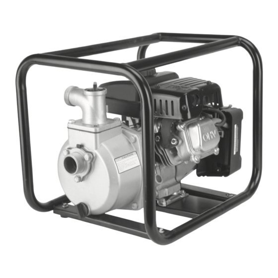
1-1/2" Gasoline Powered Clear Water Pump
Item 68328
Using an engine indoors CAN KILL YOU
IN MINUTES.
Engine exhaust contains carbon monoxide.
This is a poison you cannot see or smell.
NEVER use inside
a home or garage,
EVEN IF doors and
windows are open.
When unpacking, make sure that the product is intact and undamaged.
If any Pump parts are missing or broken, please call 1-800-444-3353 as soon as possible.
If any Engine parts are missing or broken, please call 1-800-520-0882 as soon as possible.
Record Product's Serial Number Here:
Note: If product has no serial number, record month and year of purchase instead.
Note: Some parts are listed and shown for illustration purposes only, and are not available individually
as replacement parts.
©
Copyright
2010 by Harbor Freight Tools
or form without the express written consent of Harbor Freight Tools. Diagrams within this manual may not be drawn proportionally. Due to continuing
improvements, actual product may differ slightly from the product described herein. Tools required for assembly and service may not be included.
Manual Revised 11g
Only use OUTSIDE
and far away from
windows, doors,
and vents.
Visit our website at: http://www.harborfreight.com
Email our tech support at: tech@harborfreight.com
Email our Engine support at: predator@harborfreight.com
®
. All rights reserved. No portion of this manual or any artwork contained herein may be reproduced in any shape
Advertisement
Table of Contents

Related Manuals for Pacific hydrostar Pacific Hydrostar 1-1/2" Gasoline Powered Clear Water Pump


Summary of Contents for Pacific hydrostar Pacific Hydrostar 1-1/2" Gasoline Powered Clear Water Pump
- Page 1 . All rights reserved. No portion of this manual or any artwork contained herein may be reproduced in any shape or form without the express written consent of Harbor Freight Tools. Diagrams within this manual may not be drawn proportionally. Due to continuing improvements, actual product may differ slightly from the product described herein.
-
Page 2: Specifications
Specifications Pump Suction & Discharge Size 1-1/2" NPT Discharge Capacity 75 GPM Maximum Discharge Head 79 ft. Maximum Suction Head 26 ft. Maximum Pressure 34.2 PSI Mechanical Seal Ceramic Intake Strainer Included Accessories Hose Clamps Spark Plug Wrench Engine Displacement 99cc Engine Type Horizontal Single Cylinder 4 stroke OHV... -
Page 3: Symbol Definitions
Save This Manual Symbol Definitions Keep this manual for the safety warnings and precautions, Symbol Property or Statement assembly, operating, inspection, maintenance and cleaning procedures. Write the product’s serial Revolutions Per Minute number in the front of the manual near the assembly diagram (or month and year of purchase if product WARNING marking concerning Risk has no number). -
Page 4: Operating Precautions
5. Use only lubricants and fuel recommended in 9. People with pacemakers should consult their the Specifications chart of this manual. physician(s) before use. Electromagnetic fields in close proximity to a heart pacemaker could 6. Wear ANSI-approved safety goggles, heavy-duty cause pacemaker interference or pacemaker work gloves, and dust mask/respirator during set up. failure. -
Page 5: Service Precautions
23. Before use, check for misalignment or binding 5. Maintain labels and nameplates on the of moving parts, breakage of parts, and any equipment. These carry important information. other condition that may affect the equipment’s If unreadable or missing, contact Harbor operation. - Page 6 Controls Fuel Tank Cap Fuel Tank Muffler Choke Throttle Starter Handle Air Filter Oil Dipstick Engine Switch Priming Cap Discharge Port Intake Port Water Drain Plug For Pump technical questions, please call 1-800-444-3353. Page 4 Item 68328 For Engine technical questions, please call 1-800-520-0882.
-
Page 7: Connecting Hoses
3. Slide one of the Hose Clamps over the end of the Set up suction hose (a). Slide the Hose onto the Hose Coupler (b). Use a screwdriver (not included) to tighten the Hose Clamp until secure. The emission control system for this Pump’s Engine is warranted for standards set by the U.S. - Page 8 5. For the discharge hose, slide a Hose Coupling Ring 7. Slide a Hose Clamp over the end of the Discharge over the remaining Hose Coupler (a) and place a Hose (a). Slide the Discharge Hose onto the Hose Gasket onto the end of the Hose Coupler (b) (all not Coupler (b).
- Page 9 Locating the Water Pump Locate the Water Pump on a flat, level, sturdy surface capable of supporting the weight of the Pump. 1. For best Pump performance, place the Pump near the water level and use hoses that are no longer than Strainer necessary. This will allow the Pump to produce the greatest output with the least self-priming time.
-
Page 10: Operation
Checking and Filling Engine Oil Operation CAUTION! Your Warranty is VOID if the engine’s crankcase is not properly filled with oil before Read the ENTIRE IMPORTANT SAFETY each use. before each use, check the oil level. INFORMATION section at the beginning Do not run the engine with low or no engine of this manual including all text oil. -
Page 11: Starting The Engine
Starting the Engine 1. To start a cold engine, move the Choke to the CHOKE position. To restart a warm engine, leave the Choke in the RUN position. 2. Slide the Throttle to 1/3 away from the SLOW position (the “turtle”). I ON 3. -
Page 12: Stopping The Engine
IMPORTANT: Allow the engine to run at no load for five minutes with no load after each start-up so that the engine can stabilize. 6. Adjust the Throttle as needed. 7. break-in Period: a. Breaking-in the engine will help to ensure proper equipment and engine operation. b. The operational break-in period will last about 3 hours of use. During this period: • ... -
Page 13: Maintenance Procedures
Maintenance and Service WARNING TO PREVENT SERIOUS INjURY FROM ACCIDENTAL STARTING: Turn the Power Switch of the equipment to its “OFF” position, wait for the engine to cool, and disconnect the spark plug cap before performing any inspection, maintenance, or cleaning procedures. TO PREVENT SERIOUS INjURY FROM EqUIPMENT FAILURE: Do not use damaged equipment. - Page 14 Checking and Filling Fuel WARNING! TO PREVENT SERIOUS INjURY FROM FIRE: Fill the fuel tank in a well-ventilated area away Full level Full level from ignition sources. If the engine is hot from use, shut the engine off and wait for it to cool before adding fuel.
- Page 15 Spark Plug Maintenance Spark Plug Disconnect spark plug cap from end of plug. Clean out debris from around spark plug. 2. Using a spark plug wrench, remove the spark plug. 3. Inspect the spark plug: If the electrode is oily, clean it using a clean, dry rag.
- Page 16 Storage c. After all fuel has drained, reinstall the drain bolt and tighten securely. When the equipment is to remain idle for longer than 3. LUbRICATION: 20 days, prepare the engine for storage as follows: a. Change engine oil. 1. CLEANING: Wait for engine to cool, then clean engine with b.
-
Page 17: Pump Troubleshooting
Pump Troubleshooting Problem Possible Causes Likely Solutions 1. Incorrect lubrication or 1. Lubricate using recommended oil or not enough lubrication. grease according to directions. Pump overheats 2. Worn parts. 2. Have qualified technician inspect internal mechanism and replace parts as needed. 1. Low engine speed. 1. - Page 18 Engine Troubleshooting Problem Possible Causes Probable Solutions Engine will not start FUEL RELATED: FUEL RELATED: 1. No fuel in tank or fuel valve closed. 1. Fill fuel tank and open fuel valve. 2. Choke not in CHOKE position, cold engine. 2.
- Page 19 Engine Troubleshooting (cont.) Problem Possible Causes Probable Solutions Engine misfires 1. Spark plug cap loose. 1. Check wire connections. 2. Incorrect spark plug gap or 2. Re-gap or replace spark plug. damaged spark plug. 3. Defective spark plug cap. 3. Replace spark plug cap. 4.
- Page 20 Parts List (Including Item 68124 99cc engine) Part Description Part Description Part Description Cylinder Head Lifter Vavle Subassembly Governor Rod Plate Lifter Stopper Throttle Valve Subassembly Cylinder Head Gasket Subassembly Returning Spring Cylinder Head Cover Valve Adjusting Bolt Governor Rocker Valve Subassembly Spring Nut Valve Adjusting...
- Page 21 Parts Diagram (Including Item 68124 99cc engine) For Pump technical questions, please call 1-800-444-3353. Item 68328 Page 19 For Engine technical questions, please call 1-800-520-0882.
-
Page 22: Limited 90-Day Warranty
The United States Environmental Protection Agency (herein EPA) and Harbor Freight Tools Co. makes every effort to assure that Harbor Freight Tools (herein HFT) are pleased to explain the emission control its products meet high quality and durability standards, system warranty on your 1997 and later Small Off-Road Engine (herein and warrants to the original purchaser that this product engine). - Page 23 Consequential Damages Coverage required maintenance is warranted for the period of time up to the first scheduled replacement point for that part. Any replacement part, Coverage under this warranty shall also extend to the failure of any provided it is equivalent in durability and performance, may be used in engine components caused by the failure of any warranted part while performance of maintenance or repairs.
- Page 24 Notes 3491 Mission Oaks Blvd. • PO Box 6009 • Camarillo, CA 93011 www.harborfreight.com...
Need help?
Do you have a question about the Pacific Hydrostar 1-1/2" Gasoline Powered Clear Water Pump and is the answer not in the manual?
Questions and answers