Table of Contents
Advertisement
Quick Links
Download this manual
See also:
Service Manual
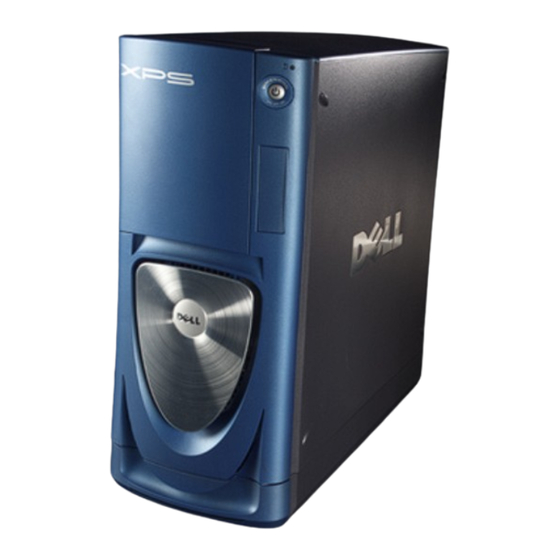
Dell™ Dimension™ XPS
serial connector 1
serial connector 2
diagnostic lights
keyboard connector
USB 2.0
connectors (6)
DVI video connector
modem
PCI sound card
with IEEE 1394
card slots
w w w . d e l l . c o m | s u p p o r t . d e l l . c o m
headphone connector
USB 2.0 connectors (2)
IEEE 1394 connector
fans
parallel connector
cover release latch
mouse connector
network adapter connector
VGA video connector
security cable slot
padlock ring
power connector
Advertisement
Table of Contents

Related Manuals for Dell XPS /Dimension


Summary of Contents for Dell XPS /Dimension
- Page 1 Dell™ Dimension™ XPS headphone connector USB 2.0 connectors (2) IEEE 1394 connector serial connector 1 fans serial connector 2 parallel connector diagnostic lights cover release latch keyboard connector mouse connector USB 2.0 network adapter connector connectors (6) VGA video connector...
-
Page 2: Abbreviations And Acronyms
Reproduction in any manner whatsoever without the written permission of Dell Computer Corporation is strictly forbidden. Trademarks used in this text: Dell, the DELL logo, DellNet, and Dimension are trademarks of Dell Computer Corporation; Intel, Pentium, and Celeron are registered trademarks of Intel Corporation;... -
Page 3: Table Of Contents
Contents Finding Information for Your Computer ....CAUTION: Safety Instructions ....General . - Page 4 Network Setup Wizard ..... . Turning Off Your Computer ....2 Optimizing Performance ®...
- Page 5 ......When to Use the Dell Diagnostics ....
- Page 6 ® Using Windows XP System Restore ....Creating a Restore Point ....Restoring the Computer to an Earlier Operating State .
- Page 7 AGP Cards ......Removing an AGP Card ..... Installing an AGP Card .
- Page 8 "Total Satisfaction" Return Policy (U.S. Only) ..Limited Warranty Terms for Dell-Branded Hardware Products (Canada Only) ......
-
Page 9: Finding Information For Your Computer
Finding Information for Your Computer Dell provides the following support options to help you quickly find answers to your questions and problems: • Dell Solution Center — Double-click the Dell Solutions Center ® ® icon on your Microsoft Windows desktop for documentation, tools, troubleshooting information, and links to online support resources. - Page 10 Find It Here • Latest drivers for my computer D e l l S u p p o r t W e b s i t e — support.dell.com • Answers to technical service and The Dell Support website provides several online tools, including: support questions •...
- Page 11 Documentation and drivers are already • My computer documentation installed on your computer when shipped from Dell. You can use the CD to reinstall • My device documentation drivers (see page 67), run the Dell Diagnostics (see page 64), or access your documentation.
- Page 12 These labels are located on your computer. •Use the Service Tag to identify your computer when you access Dell Support or when you contact Dell for technical assistance. •Enter the Express Service Code into the automated call-routing system when you contact Dell for technical assistance.
-
Page 13: Caution: Safety Instructions
CAUTION: Safety Instructions Use the following safety guidelines to help ensure your own personal safety and to help protect your computer and working environment from potential damage. General • Do not attempt to service the computer yourself unless you are a trained service technician. - Page 14 (continued) CAUTION: Safety Instructions • To avoid shorting out your computer when disconnecting a network cable, first unplug the cable from the network adapter on the back of your computer, and then from the network jack. When reconnecting a network cable to your computer, first plug the cable into the network jack, and then into the network adapter.
-
Page 15: When Using Your Computer
When Using Your Computer As you use your computer, observe the following safe-handling guidelines. CAUTION: Do not operate your computer with any cover(s) (including computer covers, bezels, filler brackets, front-panel inserts, and so on) removed. • Your computer is equipped with one of the following: –... -
Page 16: When Working Inside Your Computer
Before you open the computer cover, perform the following steps in the sequence indicated. CAUTION: Do not attempt to service the computer yourself, except as explained in your online Dell™ documentation or in instructions otherwise provided to you by Dell. Always follow installation and service instructions closely. -
Page 17: Protecting Against Electrostatic Discharge
CAUTION: Viewing the monitor screen for extended periods of time may result in eye strain. For comfort and efficiency, observe the ergonomic guidelines in the Dell™ Dimension™ Help file when setting up and using your computer. To access the help file, see page 38. -
Page 18: Battery Disposal
(continued) When Using Your Computer Battery Disposal Your computer uses a lithium coin-cell battery. The lithium coin-cell battery is a long-life battery, and it is very possible that you will never need to replace it. However, should you need to replace it, see page 115. Do not dispose of the battery along with household waste. -
Page 19: Using Your Computer
S E C T I O N 1 U s i n g Yo u r C o m p u t e r Opening the Drive Door Connecting Two Monitors Configuring Graphics Cards About Serial ATA Drives About Your RAID Configuration Transferring Information to a New Computer Copying CDs Network Setup Wizard... -
Page 20: Opening The Drive Door
Opening the Drive Door Connecting Two Monitors NOTE: If you are connecting two monitors that have VGA connectors, you must have the optional VGA adapter. If you are connecting two flat-panel monitors, at least one of them must have a VGA connector. If you are connecting a television, you may connect only one monitor (VGA or DVI) in addition to the television. - Page 21 NOTE: If your computer has integrated video, do not connect either monitor to the integrated video connector. If both monitors have VGA connectors: Connect one of the monitors to the VGA (blue) connector on the computer. Connect the other monitor to the optional VGA adapter and connect the VGA adapter to the DVI (white) connector on the computer.
-
Page 22: Configuring Graphics Cards
Configuring Graphics Cards Settings and Functions Dell configured your graphics card for optimal performance with most games and other video programs. However, some game manufacturers may recommend that you either change a setting or enable or disable a certain function for a game to properly run. You may also want to readjust settings to better fit your gaming style. -
Page 23: Removing The Graphics Card Driver
NOTE: If you reinstall the graphics card that came with your computer, the card’s drivers are located on the Dell Dimension ResourceCD (see "Drivers" on page 67 for more information). About Serial ATA Drives Your Dimension™... -
Page 24: About Your Raid Configuration
RAID configurations available in the computer industry for different types of uses, Dell offers either RAID level 0 or RAID level 1 on the Dimension XPS computer. A RAID level 0 configuration is recommended for high-performance gaming, and a RAID level 1 configuration is recommended for the data integrity requirements for digital photography and audio. -
Page 25: Raid Level 1
RAID Level 1 RAID level 1 uses a data-redundancy storage technique known as "mirroring." When data is written to the primary drive, it is then duplicated, or mirrored, on the other drive. A RAID level 1 configuration sacrifices high data access rates for its data redundancy advantages. serial ATA RAID PCI card configured for RAID level 1 segment 1... - Page 26 You can transfer the data to the new computer over a network or serial connection, or you can store it on a removable medium, such as a writable CD or floppy disk. To prepare the new computer for the file transfer: Click the Start button, point to All Programs→...
-
Page 27: Copying Cds
Copying CDs NOTE: Ensure that you follow all copyright laws when you create CDs. This section applies only to computers that have a CD- or DVD-recording device. The information in this section is based on the Roxio Easy CD Creator Basic documentation that came with your computer. -
Page 28: Using Easy Cd Creator Basic
XP Help and Support Center (see "Finding Help Information" on page 38). The documentation is also provided on the Dell Dimension ResourceCD, which is included with your computer. Each Easy CD Creator Basic project program also has thorough online help files. -
Page 29: How To Copy A Cd
How to Copy a CD NOTE: If you have a DVD/CD-RW combo drive and you experience recording problems, first check for available software patches at the Dell Support website at support.dell.com and if necessary, the Roxio support website at support.roxio.com. -
Page 30: Network Setup Wizard
Insert a blank CD into the CD-RW drive and close the tray. The recording starts automatically. After the recording completes, click OK. Network Setup Wizard ® ® The Microsoft Windows XP operating system provides a Network Setup Wizard to guide you through the process of sharing files, printers, or an Internet connection between computers in a home or small office. -
Page 31: Optimizing Performance
S E C T I O N 2 O p t i m i z i n g P e r f o r m a n c e ® Intel Performance Acceleration Technology DDR Memory and Processor Front-Side Bus Hyper-Threading Overclocking... -
Page 32: Intel ® Performance Acceleration Technology
® Intel Performance Acceleration Technology ® Your Dimension™ XPS computer is equipped with the Intel 875P chipset, which utilizes Performance Acceleration Technology (PAT). PAT is designed to optimize performance by reducing the latency between DDR 400 memory and 800 front-side bus processors, and helps provide high performance to meet the requirements for today’s demanding software. -
Page 33: Overclocking
There are several after-market "performance-modification" products available through various sources, but Dell discourages and does not support the use of those products on its computers. O p t i m i z i ng Per f o r m a n c e... - Page 34 Optimizing Pe r for mance...
-
Page 35: Solving Problems
S E C T I O N 3 S o l v i n g P r o b l e m s Finding Solutions Finding Help Information Battery Problems Drive Problems E-Mail, Modem, and Internet Problems Error Messages General Problems IEEE 1394 Device Problems Keyboard Problems Mouse Problems... -
Page 36: Finding Solutions
See page 51. Press a key or move the Dell™ mouse. See the Dimension™ Help file for information on standby mode. Get technical assistance from Dell. See page 129. See page 44. So l vi n g Pro b l em s... - Page 37 See page 57. See page 55. See page 42. See page 49. See page 49. See page 39. See page 51. See page 54. See page 44. See page 45. See page 42. See page 42. See page 45 So l vi n g Pro b l em s...
-
Page 38: Finding Help Information
(see page 115). If the battery still does not work properly, contact Dell (see page 129). So l vi n g Pro b l em s... -
Page 39: Drive Problems
Drive Problems Floppy drive problems ® — Click the Start N S U R E T H A T I N D O W S R E C O G N I Z E S T H E D R I V E button and click My Computer. -
Page 40: Cd Drive Problems
T A N D B Y M O D E I N I N D O W S B E F O R E W R I T I N G T O A — For information on power conservation modes, see the Dell™ D I S C Dimension™... -
Page 41: Dvd Drive Problems
My Computer. If the DVD drive is not listed, perform a full scan with your antivirus software to check for and remove viruses. Viruses can sometimes prevent Windows from recognizing the drive. Dell™ Dimension™ Help — See the file for instructions L E A N T H E D I S C on cleaning your DVDs. -
Page 42: E-Mail, Modem, And Internet Problems
E-Mail, Modem, and Internet Problems NOTE: Connect the modem to an analog telephone jack only. The modem does not operate while it is connected to a digital telephone network. NOTE: For optimum performance, install a modem card only in PCI slot 2, 3, or 4. —... - Page 43 ) — See your telephone U R N O F F C A L L W A I T I N G C A T C H P H O N E directory for instructions on deactivating this feature. Then adjust the dial-up networking connection properties.
-
Page 44: Error Messages
If so, run the program that you want to use first. — Contact Dell (see page 129). P E R A T I N G S Y S T E M N O T F O U N D H E F I L E B E I N G C O P I E D I S T O O L A R G E F O R T H E D E S T I N A T I O N —... -
Page 45: General Problems
General Problems The computer stops responding — If your computer locks up and you are unable U R N T H E C O M P U T E R O F F to get a response by pressing a key on your keyboard or moving your mouse, press and hold the power button for at least 8 to 10 seconds until the computer turns off. -
Page 46: A Program Is Designed For An Earlier Windows Operating System
A program is designed for an earlier Windows operating system — U N T H E R O G R A M O M P A T I B I L I T Y I Z A R D Windows XP provides a Program Compatibility Wizard that configures a program so it runs in an environment similar to non-Windows XP operating system environments. -
Page 47: Other Technical Problems
E L L website or e-mail service, call Dell for technical assistance (see page 129). See "Dell Technical Support Policy (U.S. Only)" on page 128 for a description of the hardware and software support provided by Dell. General hardware problems... -
Page 48: Ieee 1394 Device Problems
F Y O U H A V E P R O B L E M S W I T H A E L L P R O V I D E D — Contact Dell (see page 129). D E V I C E I EEE 139 4... -
Page 49: Keyboard Problems
Keyboard Problems — E S T A R T T H E C O M P U T E R • If the mouse is functioning, shut down the computer through the Start menu (see page 30). After the computer shuts down, press the power button to restart the computer. - Page 50 F Y O U C O N N E C T E D T H E M O U S E B E F O R E T U R N I N G O N T H E — C O M P U T E R R E C O N N E C T T H E M O U S E C A B L E Simultaneously press <Ctrl><Esc>...
-
Page 51: Network Problems
D J U S T T H E O W E R R O P E R T I E S hibernate mode. For information on power conservation modes, see the Dell™ Dimension™ Help file, or search for the keyword standby or hibernate in ®... - Page 52 • Ensure that the front panel cable is securely connected to the system board (see page 85). • If the problem persists, contact Dell (see page 129). — The computer is F T H E P O W E R L I G H T I S A M B E R A N D G R E E N receiving electrical power, but an internal power problem might exist.
-
Page 53: Printer Problems
• Multiple power strips connected to the same electrical outlet Printer Problems NOTE: Dell does not cover the printer’s warranty. If you need technical assistance for your printer, call the printer’s manufacturer. See the printer documentation for the correct phone number. -
Page 54: Scanner Problems
E I N S T A L L T H E P R I N T E R D R I V E R instructions. Scanner Problems NOTE: Dell does not cover the scanner’s warranty. If you need technical assistance for your scanner, call the scanner’s manufacturer. See the scanner documentation for the correct phone number. -
Page 55: Sound And Speaker Problems
® E R I F Y T H A T T H E S C A N N E R I S R E C O G N I Z E D B Y I C R O S O F T ®... -
Page 56: No Sound From Headphones
— Ensure that the electrical outlet is E S T T H E E L E C T R I C A L O U T L E T working by testing it with another device, such as a lamp. —... -
Page 57: Video And Monitor Problems
— Your headphones do not work if the CD drive is I S A B L E D I G I T A L M O D E operating in digital mode. To disable digital mode: Click the Start button, click Control Panel, and then click Sounds, Speech, and Audio Devices. -
Page 58: If The Screen Is Difficult To Read
) — If you are using a E S T T H E V I D E O E X T E N S I O N C A B L E I F U S E D video extension cable and removing the cable solves the problem, the cable is defective. -
Page 59: Advanced Troubleshooting
S E C T I O N 4 A d v a n c e d Tr o u b l e s h o o t i n g Diagnostic Lights Dell Diagnostics Drivers ® Using Windows XP System Restore Resolving Software and Hardware Incompatibilities ®... -
Page 60: Diagnostic Lights
Memory modules are detected, but a Reinstall all memory modules (see memory failure has occurred. page 86). Ensure that all the connector tabs are locked. Restart the computer. If the problem persists, contact Dell (see page 129). = yellow = green = off Advanced Troubleshooting... - Page 61 • If the problem persists or the computer has integrated video, contact Dell (see page 129). A possible floppy or hard drive failure Reseat all power and data cables and has occurred.
- Page 62 Dell (see page 129). A possible system board resource See "Resolving Software and and/or hardware failure has occurred. Hardware Incompatibilities" on page 71. If the problem persists, contact Dell (see page 129). = yellow = green = off Advanced Troubleshooting...
- Page 63 (see "Resolving Software and Hardware Incompatibilities" on page 71). If the problem persists, contact Dell (see page 129). Another failure has occurred. • Ensure that the cables are properly connected to the system board (see page 85) from the hard drive, CD drive, and DVD drive.
-
Page 64: Dell Diagnostics
NOTICE: Use the Dell Diagnostics to test your Dell™ computer only. Using this program with other computers can result in error messages. Start the Dell Diagnostics from either your hard drive (see page 64) or from the Dell Dimension ResourceCD (see page 65). - Page 65 When the boot device list appears, highlight Boot to Utility Partition and press <Enter>. When the Dell Diagnostics Main Menu appears, select the test you want to run (see page 66). Starting the Dell Diagnostics From the ResourceCD Insert the ResourceCD.
-
Page 66: Dell Diagnostics Main Menu
Dell Diagnostics Main Menu After the Dell Diagnostics loads and the Main Menu screen appears, click the button for the option you want. Option Function Express Test Performs a quick test of devices. This test typically takes 10 to 20 minutes and requires no interaction on your part. -
Page 67: Drivers
When the tests are completed, if you are running the Dell Diagnostics from the ResourceCD, remove the CD. Close the test screen to return to the Main Menu screen. To exit the Dell Diagnostics and restart the computer, close the Main Menu screen. -
Page 68: Identifying Drivers
Reinstalling Drivers NOTICE: The Dell Support website at support.dell.com and your Dell Dimension ResourceCD provide approved drivers for Dell™ computers. If you install drivers obtained from other sources, your computer might not work correctly. Using Windows XP Device Driver Rollback If a problem occurs on your computer after you install or update a driver, use Windows XP Device Driver Rollback to replace the driver with the previously installed version. -
Page 69: Using Windows ® Xp System Restore
Finish to restart the computer. When you see the Windows desktop, reinsert the ResourceCD. At the Welcome Dell System Owner screen, click Next. NOTE: The ResourceCD displays drivers only for hardware that came installed in your computer. If you installed additional hardware, the drivers for the new hardware might not be displayed by the ResourceCD. -
Page 70: Restoring The Computer To An Earlier Operating State
Restoring the Computer to an Earlier Operating State If problems occur after you install a device driver, use Device Driver Rollback (see page 68) to resolve the problem. If that is unsuccessful, then use System Restore. NOTICE: Before you restore the computer to an earlier operating state, save and close any open files and exit any open programs. -
Page 71: Resolving Software And Hardware Incompatibilities
Enabling System Restore If you reinstall Windows XP with less than 200 MB of free hard-disk space available, System Restore is automatically disabled. To see if System Restore is enabled: Click the Start button and click Control Panel. Click Performance and Maintenance. Click System. -
Page 72: Reinstalling Microsoft ® Windows ® Xp
Therefore, do not reinstall Windows XP unless instructed to do so by a Dell technical support representative. NOTICE: To prevent conflicts with Windows XP , disable any virus protection software installed on your computer before you reinstall Windows XP . - Page 73 Press the arrow keys to select CD-ROM, and then press <Enter>. When the message appears, press any key. Press any key to boot from CD Windows XP Setup When the Windows XP Setup screen appears, press <Enter> to select To set up Windows now.
-
Page 74: Reinstalling Drivers And Software
If the Networking Settings screen appears, click Typical and click Next. If you are reinstalling Windows XP Professional and you are prompted to provide further information regarding your network configuration, enter your selections. If you are unsure of your settings, accept the default selections. Windows XP installs the operating system components and configures the computer. -
Page 75: Removing And Installing Parts
S E C T I O N 5 R e m o v i n g a n d I n s t a l l i n g Pa r t s Front and Back View of the Computer Before You Begin Opening the Computer Cover Inside View of Your Computer... -
Page 76: Front And Back View Of The Computer
Front and Back View of the Computer Front View hard-drive activity light The hard-drive light is on when the computer reads data from or writes data to the hard drive. The light might also be on when a device such as your CD player is operating. -
Page 77: Front View (Doors Open)
Front View (Doors Open) headphone connector Use the headphone connector to attach headphones and most kinds of speakers for listening to all sounds in your computer, including your CD player and system sounds such as beeps. USB 2.0 connectors (2) Use the front USB connectors for devices that you connect occasionally, such as joysticks or cameras. -
Page 78: Back View
Back View microprocessor fans (2) For optimal cooling, two microprocessor fans are provided. Do not block the vents. cover release latch To open the computer, lay the computer on its side with the cover release latch at the top and then push the latch to the left. See "Opening the Computer Cover" on page 82. - Page 79 card slots Access connectors for any installed PCI (4 slots) and AGP cards (1 slot). PCI sound card with • Line-in connector — Use the blue line-in connector to attach a record/playback IEEE 1394 device such as a cassette player, CD player, or VCR. •...
-
Page 80: Before You Begin
13 USB 2.0 connectors (6) Use the back USB connectors for devices that typically remain connected, such as printers and keyboards. It is recommended that you use the front USB connectors for devices that you connect occasionally, such as joysticks or cameras. 14 keyboard connector If you have a standard keyboard, plug it into the purple keyboard connector. -
Page 81: Precautionary Measures
13. CAUTION: Do not attempt to service the computer yourself, except as explained in your online Dell™ documentation or in instructions otherwise provided to you by Dell. Always follow installation and service instructions closely. NOTICE: To help avoid possible damage to the system board, wait 5 seconds (or wait until the... -
Page 82: Protecting Against Electrostatic Discharge
• Handle components and cards with care. Do not touch the components or contacts on a card. Hold a card by its edges or by its metal mounting bracket. Hold a component such as a microprocessor chip by its edges, not by its pins. Protecting Against Electrostatic Discharge Static electricity can harm delicate components inside your computer. - Page 83 Lay the computer on its side with the cover release latch on the top as shown in the following figure. Open the computer cover: Slide the cover release latch toward the top of the computer. Raise the cover, and pivot it toward the front of the computer. cover release latch security cable slot padlock ring...
-
Page 84: Inside View Of Your Computer
Inside View of Your Computer floppy drive CD/DVD drive hard drive microprocessor airflow shroud card fan microprocessor fans (2) system board power supply power supply fans (2) Re m ov i n g a n d I ns t al l i n g Pa r t s... -
Page 85: System Board Components
System Board Components password jumper (PASSWORD) SCSI_LED header (SCSI_LED) front-panel connector hard-drive connector (IDE1) battery socket (FRONT_PANEL) (BATTERY) secondary drive connector (SEC_IDE) standby power light floppy-drive connector (FDD) (PWR_LED) serial ATA connector memory module (SATA_1) connectors (2, 4) internal speaker (SPKR) power connector clear CMOS jumper (PWR) -
Page 86: Memory
Memory You can increase your computer memory by installing memory modules on the system board. For information on the type of memory supported by your computer, see "Memory" on page 120. NOTE: DDR 333 memory operates at 320-MHz when used with an 800-MHz front-side bus processor. -
Page 87: Memory Installation Guidelines
NOTICE: If you remove your original memory modules from the computer during a memory upgrade, keep them separate from any new modules that you may have, even if you purchased the new modules from Dell. You should install your original memory modules in pairs either in do not connectors DIMM1 and DIMM2 or connectors DIMM3 and DIMM4. - Page 88 To insert a module, press out the securing clip at each end of the memory module connector. memory connector closest to microprocessor securing clips (2) connector Align the notch on the bottom of the module with the crossbar in the connector. notch memory module cutouts (2)
-
Page 89: Pci Cards
CAUTION: Before you begin any of the procedures in this section, follow the safety instructions on page 13. Your Dell™ computer provides slots for up to four 32-bit, 33-MHz cards. For more information, see "Specifications" on page 120. NOTE: For optimum performance, install a PCI sound card only in PCI slot 3 or 4 and a modem card only in PCI slot 2, 3, or 4. - Page 90 filler bracket card lever edge connector card connector retention arm If you are installing a new card, remove the filler bracket to create a card-slot opening. Then continue with step 7. If you are replacing a card that is already installed in the computer, remove the card (see page 92).
- Page 91 not fully seated card fully seated card bracket within slot bracket caught outside of slot Before you lower the retention arm, ensure that: • The tops of all cards and filler brackets are flush with the alignment bar. • The notch in the top of the card or filler bracket fits around the alignment guide. Press the retention arm into place, securing the card(s) in the computer.
-
Page 92: Removing A Pci Card
filler bracket alignment guide alignment bar retention arm NOTICE: Do not route card cables over or behind the cards. Cables routed over the cards can prevent the computer cover from closing properly or cause damage to the equipment. Connect any cables that should be attached to the card. See the documentation for the card for information about the card’s cable connections. -
Page 93: Agp Cards
If you are removing the card permanently, install a filler bracket in the empty card-slot opening. If you need a filler bracket, contact Dell (see page 129). NOTE: You must install filler brackets over empty card-slot openings to maintain FCC certification of the computer. -
Page 94: Installing An Agp Card
AGP card lever edge connector AGP connector PCI connector retention arm Pull the card up and out of the card clip. Installing an AGP Card Follow the instructions in "Before You Begin" on page 80. Open the computer cover (see page 82). Press the lever on the card retention arm and raise the retention arm. -
Page 95: Drives
AGP card lever edge connector AGP connector PCI connector retention arm Gently press the card into the AGP connector until it clicks into place, ensuring that the tab fits into the notch on the front end of the card. Lower the retention arm and press it into place, securing the card(s) in the computer. Close the computer cover (see page 117). -
Page 96: Hard Drive
floppy drive CD/DVD drives hard drives Hard Drive CAUTION: Before you begin any of the procedures in this section, follow the safety instructions page 13. Removing a Hard Drive Follow the instructions in "Before You Begin" on page 80. Open the computer cover (see page 82). Disconnect the power and hard-drive cables from the drive. - Page 97 power cable power cable tabs (2) tabs (2) serial ATA IDE hard- hard drive drive cable serial ATA hard- IDE hard drive cable drive system board connector system board connector IDE hard drive example serial ATA hard drive example Press in on the tabs on each side of the drive and slide the drive up and out. Installing a Hard Drive Unpack the replacement hard drive, and prepare it for installation.
- Page 98 If your replacement hard drive does not have the bracket rails attached, remove the rails from the old drive by removing the two screws that secure each rail to the drive. Attach the bracket rails to the new drive by aligning the screw holes on the drive with the screw holes on the bracket rails and then inserting and tightening all four screws (two screws on each rail).
- Page 99 power cable power cable tabs (2) tabs (2) serial ATA IDE hard- hard drive drive cable serial ATA hard- IDE hard drive cable drive system board connector system board connector IDE hard drive example serial ATA hard drive example Connect the power and hard-drive cables to the drive. Check all connectors to be certain that they are properly cabled and firmly seated.
-
Page 100: Floppy Drive
Floppy Drive CAUTION: Before you begin any of the procedures in this section, follow the safety instructions page 13. Removing a Floppy Drive Follow the instructions in "Before You Begin" on page 80. Open the computer cover (see page 82). Disconnect the power and floppy-drive cables from the back of the floppy drive. - Page 101 Installing a Floppy Drive Follow the instructions in "Before You Begin" on page 80. Open the computer cover (see page 82). If you are replacing a drive and the the new drive does not have the bracket rails attached, remove the rails from the old drive by removing the two screws that secure each rail to the drive.
-
Page 102: Cd/Dvd Drive
If you are installing a new floppy drive rather than replacing a drive, remove the front- panel inserts. From inside the drive bay, gently press on each side of the insert until it pops out. Check all cable connections, and fold cables out of the way to provide airflow for the fan and cooling vents. - Page 103 power cable tabs (2) CD/DVD drive cable CD/DVD drive audio cable* * Some drives do not have this cable. Press inward on the two tabs on the sides of the drive, and then slide the drive upward and remove it from the drive bay. Installing a CD/DVD Drive Follow the instructions in "Before You Begin"...
- Page 104 Connect the new drive to the set of rails that are attached to the inside of the cover. If a set of rails is not attached inside the computer cover, contact Dell (see page 129). If you are installing a replacement drive and the new drive does not have the bracket rails attached, remove the rails from the old drive by removing the two screws that secure each rail to the drive.
-
Page 105: Microprocessor Airflow Shroud
If you are installing a new CD/DVD drive rather than replacing a drive, remove the front-panel inserts. From inside the drive bay, gently press on each side of the insert until it pops out. If you are installing a drive that has its own controller card, install the controller card in an expansion slot. -
Page 106: Installing The Microprocessor Airflow Shroud
airflow shroud top anchor tabs (2) side anchor tabs (2) indentations bottom anchor tabs (2) Installing the Microprocessor Airflow Shroud Follow the instructions in "Before You Begin" on page 80. Open the computer cover (see page 82). Insert the bottom anchor tabs into the anchor slots. Align and insert the side anchor tabs into the anchor slots. -
Page 107: Microprocessor
Microprocessor CAUTION: Before you perform this procedure, follow the safety instructions on page 13. Installing the Microprocessor NOTE: It is recommended that only a technically knowledgeable person perform this procedure. CAUTION: The processor can get very hot during normal operation. Ensure that the processor has had sufficient time to cool before you touch it. - Page 108 When the heat sink is secured, pivot the rentention module clip back until the tab snaps into place to secure the heat sink. If you installed a microprocessor replacement kit from Dell, return the original heat sink assembly and microprocessor to Dell in the same package in which your replacement kit was sent.
-
Page 109: Removing The Microprocessor
NOTICE: Lay the heat sink down with the thermal grease facing upward. NOTICE: If you are installing a microprocessor upgrade kit from Dell, discard the original heat sink. If you are installing a microprocessor upgrade kit from Dell, reuse the original heat sink when you install your new microprocessor. -
Page 110: Front Panel
NOTICE: Be careful not to bend any of the pins when you remove the microprocessor from the socket. Bending the pins can permanently damage the microprocessor. release lever microprocessor socket Remove the microprocessor from the socket. If you are replacing the microprocessor, leave the release lever extended in the release position so that the socket is ready for the new microprocessor and go to "Installing the Microprocessor"... -
Page 111: Replacing The Front Panel
Disconnect and remove all disk drives (see "Drives" on page 95). Release the front panel by pressing each of the front-panel release tabs. There are seven release tabs. Close the computer cover halfway and pull the front panel away from the computer. Replacing the Front Panel To replace the front panel, perform the removal procedure in reverse. -
Page 112: Drive Door
Drive Door CAUTION: Before you begin any of the procedures in this section, follow the safety instructions on page 13. Removing the Drive Door Open the drive door. Re m ov i n g a n d I ns t al l i n g Pa r t s... - Page 113 Unsnap the top bracket hinge and pull the top of the drive door outward, away from the computer. top bracket hinge bottom bracket hinge Lift the bottom bracket hinge away from the computer. Rem ov i ng a n d I n s t a l l i n g Par t s...
-
Page 114: Replacing The Drive Door
Replacing the Drive Door To prevent damage to your computer, the drive door is designed to "break away" from the computer if it is opened too far. If the drive door detaches from the computer without disassembling, perform the removal procedure in reverse. If the drive door is open and it is opened too far, instead of breaking away from the computer in one piece, the drive door may disassemble into several smaller pieces. -
Page 115: Battery
Attach the door bracket/door hinge assembly to the door, starting with the lower part of each door hinge. door bracket/door hinge assembly door lower part of the door hinge Attach the drive door to the computer, starting with the bottom bracket hinge. Battery CAUTION: Before you begin this procedure, follow the safety instructions on page 13. - Page 116 To replace the battery: Record all the screens in the system setup program (see page 124) so that you can restore the correct settings in step 9. Follow the instructions in "Before You Begin" on page 80. Open the computer cover (see page 82). Locate the battery socket (see page 85).
-
Page 117: Closing The Computer Cover
Enter the system setup program (see page 124) and restore the settings you recorded in step 1. Properly dispose of the old battery (see page 18). Closing the Computer Cover Ensure that all cables are connected, and fold cables out of the way. Ensure that no tools or extra parts are left inside the computer. - Page 118 If you are using a padlock to secure your computer, install the padlock. NOTICE: To connect a network cable, first plug the cable into the network wall jack and then plug it into the computer. Connect your computer and devices to electrical outlets, and turn them on. Re m ov i n g a n d I ns t al l i n g Pa r t s...
-
Page 119: Appendix
S E C T I O N 6 A p p e n d i x Specifications Standard Settings Clearing Forgotten Passwords Dell Technical Support Policy (U.S. Only) Contacting Dell Regulatory Notices Limited Warranties and Return Policy... -
Page 120: Specifications
Specifications Microprocessor ® ® Microprocessor type Intel Pentium Level 1 (L1) cache 8 KB Level 2 (L2) cache 512-KB Memory Type 400- and 333-MHz DDR SDRAM Memory connectors four Memory capacities 128-, 256-, or 512- non–ECC Minimum memory 256 MB Maximum memory 2 GB BIOS address... - Page 121 Expansion Bus Bus type PCI and AGP Bus speed PCI: 33-MHz AGP: 133-MHz AGP: connector connector size 172 pins connector data width (maximum) 32 bits bus protocols 8x/4x/2x modes at 1.5 V PCI: connector four connector size 120 pins connector data width (maximum) 32 bits Drives Externally accessible...
- Page 122 Connectors External connectors: Serial two 9-pin connectors; 16550C- compatible Parallel 25-hole connector (bidirectional) Network adapter 10/100/1000 Ethernet connector PS/2 (keyboard and mouse) 6-pin mini-DIN two front-panel and six back-panel USB 2.0–compliant connectors headphones one front-panel connector System board connectors: Primary IDE drive 40-pin connector Secondary IDE drive 40-pin connector...
- Page 123 Power DC power supply: Wattage 460 W Heat dissipation 1000 BTU/hr Voltage (see page 15 for important fixed-voltage power supply—110 V at voltage setting information) 50/60 Hz manual selection and auto-sensing power supplies—90 to 135 V at 50/60 Hz; 180 to 265 V at 50/60 Hz; 100 V at 50/60 Hz for Japanese computers Backup battery 3-V CR2032 lithium coin cell...
-
Page 124: Standard Settings
Environmental Storage nonoperating (half-sine pulse) 105 G, 2 nonoperating (faired-square wave) 27 G with a velocity change of 508 cm/sec (200 inches/sec) Altitude: Operating –15.2 to 3048 m (–50 to 10,000 ft) Storage –15.2 to 10,668 m (–50 to 35,000 ft) Standard Settings The system setup program contains the standard settings for your computer. -
Page 125: Viewing Settings
Viewing Settings Turn on (or restart) your computer. When the blue DELL™ logo appears, press <F2> immediately. If you wait too long and the operating system logo appears, continue to wait until you ® ® see the Microsoft Windows desktop. Then shut down your computer and try again. -
Page 126: System Setup Screens
You can use this feature, for example, to tell the computer to boot from the CD drive so that you can run the Dell Diagnostics on the Drivers and Utilities CD, but you must set the computer to boot from the hard drive when the diagnostic tests are complete. -
Page 127: Clearing Forgotten Passwords
Changing Boot Sequence for Future Boots Enter the system setup program (see page 125). Use the arrow keys to highlight the Boot Sequence menu option and press <Enter> to access the pop-up menu. NOTE: Write down your current boot sequence in case you want to restore it. Press the up- and down-arrow keys to move through the list of devices. -
Page 128: Dell Technical Support Policy (U.s. Only)
All Dell-standard components included in a Custom Factory Integration (CFI) project are covered by the standard Dell limited warranty for your computer. However, Dell also extends a parts replace- ment program to cover all nonstandard, third-party hardware components integrated through CFI for the duration of the computer’s service contract. -
Page 129: Definition Of "Dell-Installed" Software And Peripherals
Definition of "Third-Party" Software and Peripherals Third-party software and peripherals include any peripheral, accessory, or software program sold by Dell not under the Dell brand (printers, scanners, cameras, games, and so on). Support for all third-party software and peripherals is provided by the original manufacturer of the product. - Page 130 International Access Code Website and E-Mail Address Local Numbers, and Country Code Toll-Free Numbers City Code Canada (North York, Ontario) Online Order Status: www.dell.ca/ostatus International Access Code: 011 AutoTech (automated technical support) toll-free: 1-800-247-9362 TechFax toll-free: 1-800-950-1329 Customer Care (Home Sales/Small Business) toll-free: 1-800-847-4096 Customer Care (med./large business, government)
- Page 131 Dell Outlet Store (Dell refurbished computers) toll-free: 1-888-798-7561 Software and Peripherals Sales toll-free: 1-800-671-3355 Spare Parts Sales toll-free: 1-800-357-3355 Extended Service and Warranty Sales toll-free: 1-800-247-4618 toll-free: 1-800-727-8320 Dell Services for the Deaf, Hard-of-Hearing, or toll-free: 1-877-DELLTTY Speech-Impaired (1-877-335-5889) Appendix...
-
Page 132: Regulatory Notices
Limited Warranties and Return Policy Dell-branded hardware products purchased in the U.S. or Canada come with either a 90-day, 1-year, 2-year, 3-year, or 4-year limited warranty. To determine which warranty came with your hardware product(s), see your packing slip or invoice. -
Page 133: Limited Warranty For Dell-Branded Hardware Products (U.s. Only)
Limited Warranty for Dell-Branded Hardware Products (U.S. Only) What is covered by this limited warranty? This limited warranty covers defects in materials and workmanship in your—our end-user customer's—Dell- branded hardware products, including Dell-branded peripheral products. What is not covered by this limited warranty? This limited warranty does not cover: •... - Page 134 The limited warranty on all Dell-branded products begins on the date of the packing slip or invoice. The warranty period is not extended if we repair or replace a warranted product or any parts. Dell may change the availability of limited warranties, at its discretion, but any changes will not be retroactive.
- Page 135 We are not responsible for lost or corrupted data. What if I purchased a service contract? If your service contract is with Dell, service will be provided to you under the terms of the service agreement. Please refer to that contract for details on how to obtain service.
-
Page 136: Total Satisfaction" Return Policy (U.s. Only)
"Total Satisfaction" return policy for most products that you—the end-user customer—purchase directly from Dell. Under this policy, you may return to Dell products that you purchased directly from Dell for a credit or a refund of the purchase price paid, less shipping and handling and applicable restocking fees as follows: •... - Page 137 90 days. The limited warranty begins on the date of the packing slip or invoice. The warranty period is not extended if we repair or replace a warranted product or any parts. Dell may change the terms and availability of limited warranties, at its discretion, but any changes will not be retroactive (that is, the warranty terms in place at the time of purchase will apply to your purchase).
- Page 138 During the 90 days of the 90-day limited warranty and the first year of all other limited warranties: During the 90 days of the 90-day limited warranty and the first year of all other limited warranties, we will repair any Dell- branded hardware products returned to us that prove to be defective in materials or workmanship.
-
Page 139: Total Satisfaction" Return Policy (Canada Only)
What if I purchased a service contract? If your service contract is with Dell, service will be provided to you under the terms of the service contract. Please refer to that contract for details on how to obtain service. Dell's service contracts can be found online at www.dell.ca or by calling Customer Care at 1-800-847-4096. -
Page 140: Dell Software And Peripherals (Canada Only)
While Dell offers a wide selection of software and peripheral products, we do not specifically test or guarantee that all of the products we offer work with any or all of the various models of Dell computers, nor do we test or guarantee all of the products we sell on the hundreds of different brands of computers available today. -
Page 141: 1-Year End-User Manufacturer Guarantee (Latin America And The Caribbean Only)
Latin America or the Caribbean, will be free from defects in materials, workmanship, and design affecting normal use, for a period of 1 year from the original purchase date. Products for which proper claims are made will, at Dell’s option, be repaired or replaced at Dell’s expense. Dell owns all parts removed from repaired products. Dell uses new and reconditioned parts made by various manufacturers in performing repairs and building replacement products. - Page 142 Coyancura 2283, Piso 3- Of.302, Providencia, Santiago - Chile Dell Computer de Colombia Corporation Carrera 7 #115-33 Oficina 603 Bogota, Colombia Dell Computer de Mexico SA de CV Paseo de la Reforma 2620 - 11° Piso Col. Lomas Altas 11950 México, D.F. Appendix...
-
Page 143: Intel ® Warranty Statement For Pentium ® And Celeron ® Processors Only (U.s. And Canada Only)
® ® ® Intel Warranty Statement for Pentium and Celeron Processors Only (U.S. and Canada Only) Intel’s Three Year Limited Warranty Limited Warranty ® ® Intel warrants that its family of Pentium and Celeron processors, if properly used and installed, will be free from defects in materials and workmanship and will substantially conform to Intel’s publicly available specifications for a period of three (3) years after the date the Pentium or Celeron processor was purchased (whether purchased separately or as part of a computer system). - Page 144 ® ® Intel Pentium and Celeron Processors are backed by a three-year limited warranty. Please refer to the reverse side of this card for complete warranty details. Intel’s Commitment to Quality Intel is committed to producing the highest quality processors available. That’s why we have hundreds of people dedicated to continuously improve our design, manufacturing, and testing technology.
-
Page 145: Index
60 network, 79 BIOS display. See monitor parallel, 80 clearing passwords, 127 documentation, 9 power, 78 settings, 124 Dell Dimension Help file, 11 serial, 80 finding, 9 sound, 79 online, 10 USB, 77, 80 Owner’s Manual, 10 video, 78-79 cards... - Page 146 41 lights removing, 96 removing, 102 back of computer, 60 hardware diagnostic, 60 conflicts, 71 hard-drive activity, 76 Dell Diagnostics, 64 problems, 47 electrostatic discharge Hardware Troubleshooter, 71 See ESD, 17 headphone memory e-mail connector, 77 installation guidelines, 87...
- Page 147 Windows XP , 72 CD-RW drive, 40 Program Compatibility overclocking, 33 computer crashes, 45-46 Wizard, 46 computer stops responding, 45 conflicts, 71 Dell Diagnostics, 64 diagnostic lights, 60 padlock ring, 78 drives, 39 regulatory notices, 132 passwords DVD drive, 41 reinstalling...
- Page 148 25 connectors, 79 help, accessing, 38 problems, 55 troubleshooting Hyper-Threading, 32 volume, 55 conflicts, 71 Network Setup Wizard, 30 Dell Diagnostics, 64 speaker Program Compatibility diagnostic lights, 60 problems, 55 Wizard, 46 Hardware Troubleshooter, 71 volume, 55 reinstalling, 72...
Need help?
Do you have a question about the XPS /Dimension and is the answer not in the manual?
Questions and answers