
Related Manuals for Navman TRACKFISH 6500


Summary of Contents for Navman TRACKFISH 6500
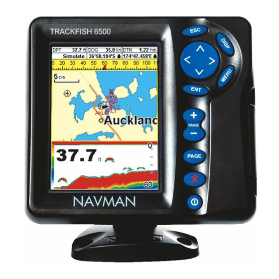
- Page 1 TRACKF I S H 6500 CHARTPLOTTER and FISHFINDER Installation and Operation Manual NAVMAN...
- Page 2 FCC Statement Note: This equipment has been tested and found to comply with the limits for a Class B digital device, pursuant to Part 15 of the FCC Rules. These limits are designed to provide reasonable protection against harmful interference in a normal installation. This equipment generates, uses and can radiate radio frequency energy and, if not installed and used in accordance with the instructions, may cause harmful interference to radio communications.
-
Page 3: Table Of Contents
7-1 Satellite display ..............31 NAVMAN TRACKFISH 6500 Installation and Operation Manual... - Page 4 17-5 Setup > Fuel ..............62 NAVMAN TRACKFISH 6500 Installation and Operation Manual...
- Page 5 18-7 Installation: Navman petrol/gasoline sensors ........
- Page 6 NAVMAN NZ LIMITED DISCLAIMS ALL LIABILITY FOR ANY USE OF THIS PRODUCT IN A WAY THAT MAY CAUSE ACCIDENTS, DAMAGE OR THAT MAY VIOLATE THE LAW.
-
Page 7: Introduction
What to do when you add or remove fuel 12-1 Sounder Overview of the depth sounder Sounder Depth, bottom features, water features Sounder Fishfinder Sounder Other boats Track your buddy, polling other boats DSC VHF Distress calls DSC VHF NAVMAN TRACKFISH 6500 Installation and Operation Manual... -
Page 8: Overview
1-1 Overview The NAVMAN TRACKFISH 6500 is a compact, DSC/Buddy track functions require a rugged, highly integrated marine chartplotter Navman DSC VHF radio with Buddy track and fishfinder. It is easy to use and has an easy support to be installed. -
Page 9: Removing And Replacing The Display Unit
Push the attached dust covers over the exposed ends of the connectors. Store the display unit in a dry clean place, such as the optional Navman carry bag. Replacing the display unit Remove the dust covers from the connectors. Plug the connectors into the... -
Page 10: Basic Operation
Goto cursor, then press Using the menus Changing data Operate the TRACKFISH by selecting items from First press to move the highlight to the menus. Items can be submenus, commands data to change, then: or data. NAVMAN TRACKFISH 6500 Installation and Operation Manual... -
Page 11: Turning On And Off / Auto Power
• If Auto power off (see section 17-1) is the display turns off. the TRACKFISH stays on when you turn the boat’s ignition switch off. You can now turn the TRACKFISH off manually. NAVMAN TRACKFISH 6500 Installation and Operation Manual... -
Page 12: Backlight And Night Mode
(see sections 3-1-1 and 3-1-2). chart after the MOB has been cancelled. To If the NMEA output (autopilot) is on, the delete the MOB waypoint, see section 5-2-5. TRACKFISH asks if the autopilot is active. NAVMAN TRACKFISH 6500 Installation and Operation Manual... -
Page 13: Alarms
To start and stop Simulate mode, and for more information, see section 17-14. In simulate mode, Simulate or Demo flashes at the bottom of the display. Warning: Never have Simulate mode on when the TRACKFISH is navigating on the water. NAVMAN TRACKFISH 6500 Installation and Operation Manual... -
Page 14: The Main Displays
1-1). to select the display from the list, then press Chart menu and displays Note The sonar displays require sonar to be installed. NAVMAN TRACKFISH 6500 Installation and Operation Manual... - Page 15 Note system to be installed. For information on Press to go from a SmartCraft display using SmartCraft, see the SmartCraft Gateway back to your last chart or sonar display. Installation and Operation Manual. NAVMAN TRACKFISH 6500 Installation and Operation Manual...
- Page 16 Other menu and displays Note Press to go from an Other display back to your last chart or sonar display. The DSC/Buddy track display requires a VHF radio to be installed. NAVMAN TRACKFISH 6500 Installation and Operation Manual...
- Page 17 (see section 17-13). Press To change the display to the next favourite, Chart + sonar, third favourite press . For example, with four Press favourites: Fourth favourite display Press NAVMAN TRACKFISH 6500 Installation and Operation Manual...
-
Page 18: Navigation: Chart
The chart display shows the chart, the boat’s position course and navigation data. 3-1 Introduction to navigating The TRACKFISH has two ways of navigating, going straight to a point or following a route. NAVMAN TRACKFISH 6500 Installation and Operation Manual... - Page 19 Create a waypoint at the and select Goto. start of the trip for you to navigate back to (see Press section 5-2-1). Going to a point on the chart Switch to a chart display. NAVMAN TRACKFISH 6500 Installation and Operation Manual...
- Page 20 0.025 nm of the waypoint or when the boat passes the waypoint or if you skip the waypoint. NAVMAN TRACKFISH 6500 Installation and Operation Manual...
-
Page 21: Chart Display
Boat course and CDI lines (see Appendix C, CDI). The boat is going to the waypoint called FISH6 G Distance and bearing of cursor from boat H Land The cursor (see section 3-2-1) A typical waypoint (see section 5) NAVMAN TRACKFISH 6500 Installation and Operation Manual... - Page 22 Then follow step 3 above. cursor symbol to show this: 36° 29.841’ N or S Latitude 175° 09.012’ E or W Longitude NAVMAN TRACKFISH 6500 Installation and Operation Manual...
-
Page 23: Distance And Bearing Calculator
(COG), speed and a specified time. To turn Projected course on and off and to set the time, see section 17-2. A Projected position Boat’s projected course C Boat position NAVMAN TRACKFISH 6500 Installation and Operation Manual... -
Page 24: Tracks And Tracking
CDI scale G The boat position is at the bottom, centre of the display Warning: The highway display does not show land, dangerous waters or chart symbols. NAVMAN TRACKFISH 6500 Installation and Operation Manual... -
Page 25: Navigation: Waypoints
If there are more waypoints than will fit on the display, press to scroll up or down a page at a time. NAVMAN TRACKFISH 6500 Installation and Operation Manual... -
Page 26: Managing Waypoints
Editing a waypoint from the chart display to highlight the waypoint to delete. Press and select Delete. In the chart display, move the cursor to the waypoint to edit. Select Yes to confirm. NAVMAN TRACKFISH 6500 Installation and Operation Manual... -
Page 27: Navigation: Routes
To go to the routes display, press , select Other, then select Routes. If there are more routes than will fit on the display, press to scroll up or down a page at a time. NAVMAN TRACKFISH 6500 Installation and Operation Manual... -
Page 28: Managing Routes
Press to complete the route display and press Menu options while creating a route: Change the name if necessary. To add a waypoint to the route iii Press and select Add. Press NAVMAN TRACKFISH 6500 Installation and Operation Manual... - Page 29 Press and select Edit. The selected route is displayed: the route name and a list of the waypoints. Edit the route as described in section 6-2-1 B, starting at step 3. NAVMAN TRACKFISH 6500 Installation and Operation Manual...
-
Page 30: Satellites
10 m (33 ft) for 95% of the time. A GPS receiver GPS antenna can receive signals from the GPS Navman GPS units have a sensitive 12-channel satellites when it is almost anywhere on earth. receiver, which tracks signals from all GPS... -
Page 31: Satellite Display
The depth eventually disappearing off the display. of the object or bottom is calculated by the NAVMAN TRACKFISH 6500 Installation and Operation Manual... -
Page 32: Interpreting The Display
If the boat is anchored, the echoes all come from the same area of bottom. This produces a flat bottom trace on the display. The screen shot shows a typical sonar display with the Fish symbols turned Off. NAVMAN TRACKFISH 6500 Installation and Operation Manual... - Page 33 50 kHz it is approximately 45°, and at 200 kHz it is approximately 11°. The differences in the cone width affect what is displayed. See section 8-3. 1000 NAVMAN TRACKFISH 6500 Installation and Operation Manual...
-
Page 34: Single And Dual Frequency Fishfinding
Therefore, it gives excellent bottom NAVMAN TRACKFISH 6500 Installation and Operation Manual... - Page 35 To use 50/200 kHz, select the Split 50/200 Wide angle, less detailed 50 kHz cone display (see section 9-4). Comparison of the same fish scenario displayed at different frequencies: 1 minute ago 30 seconds ago NAVMAN TRACKFISH 6500 Installation and Operation Manual...
- Page 36 50 kHz display 200 kHz display 200/50 Khz display Mixed display NAVMAN TRACKFISH 6500 Installation and Operation Manual...
-
Page 37: Fish Detection And Display
Wave motion may result in distorted fish cone-shaped ultrasonic pulse is displayed as arches. a fish arch. The 50 kHz frequency uses a wider Fun fish symbol Normal fish symbol Fun symbol + depth Fish arch NAVMAN TRACKFISH 6500 Installation and Operation Manual... -
Page 38: Range
Manual range is useful if the bottom depth changes rapidly, because Auto range will cause the display to change range frequently. NAVMAN TRACKFISH 6500 Installation and Operation Manual... -
Page 39: Gain And Threshold
(see section 9-5). The gain window To display or change the current settings for gain, select a sonar display and press Select Threshold to display the thresholds. This display is called the gain window. NAVMAN TRACKFISH 6500 Installation and Operation Manual... -
Page 40: Sonar Fishfinding: Displays
Optional compass (see section 2-7-4) C Depth D Colour bar Bottom Range G Fish symbols with depth H Depth line Surface The display scrolls from right (most recent echoes) to left (oldest echoes). NAVMAN TRACKFISH 6500 Installation and Operation Manual... -
Page 41: Sonar Zoom Display
Use the keys to adjust the zoom range. • The TRACKFISH calculates the zoom depth automatically. It is not necessary to turn Bottom lock on for this display. A Zoomed bottom signal Sonar history NAVMAN TRACKFISH 6500 Installation and Operation Manual... -
Page 42: Sonar 50/200 Display
A vertical line showing the gain setting; echoes above this strength will display as the maximum signal strength Use the A-Scope while adjusting the gain and threshold settings manually (see section 8-6). NAVMAN TRACKFISH 6500 Installation and Operation Manual... - Page 43 Adjust threshold so that it is just to the right of the noise. Press to close the gain window. If required, repeat these steps to adjust gain and threshold for the other frequency. NAVMAN TRACKFISH 6500 Installation and Operation Manual...
-
Page 44: Gauges Display
Select a data item that is available on your system. iii Repeat the above step to set the other gauges. Press to return to the Gauges display. NAVMAN TRACKFISH 6500 Installation and Operation Manual... -
Page 45: Data Display
Select a data item that is available on your system or select None to leave the field empty. Repeat the above step to set the other data fields. Press NAVMAN TRACKFISH 6500 Installation and Operation Manual... -
Page 46: Fuel Functions And Display
C When you remove fuel Repeat procedure B, but subtract the fuel you have removed from the original amount of fuel in the tank to calculate the amount of fuel now in the tank. NAVMAN TRACKFISH 6500 Installation and Operation Manual... -
Page 47: Fuel Display
Economy is the distance travelled per unit of fuel used. The TRACKFISH calculates this from the boat speed and fuel used. The bigger this number, the better the fuel economy Range The estimated boat range at the current fuel flow. NAVMAN TRACKFISH 6500 Installation and Operation Manual... -
Page 48: Fuel Consumption Curves
The TRACKFISH then asks you to set the throttle to achieve a target RPM. For a twin engine boat set both engines to about the target RPM. When the engine RPMs are correct, the Target RPM box will turn green. NAVMAN TRACKFISH 6500 Installation and Operation Manual... - Page 49 For a twin engine boat, keep the RPM of both engines similar while using a curve. More information about fuel consumption curves is available in Navman’s Diesel flow sensors installation and operation manual. Displaying a curve To go to the Fuel display, press select Other, then select Fuel.
-
Page 50: Tides Display
Tide height cursor, a horizontal dotted line. Press to move cursor up and down. M Height of cursor on the tide chart N Moon phase for moon at the current time on the chosen date NAVMAN TRACKFISH 6500 Installation and Operation Manual... -
Page 51: User Card Display
If a new route has the same name as an if required. The new file appears in the existing route but has different data then file list. the TRACKFISH asks which route to keep. NAVMAN TRACKFISH 6500 Installation and Operation Manual... -
Page 52: Dsc/Buddy Track Displays
Card. Press Select Read. 15 DSC/Buddy track displays Buddy track requires an optional Navman DSC VHF radio to be installed. Buddy track tracks other boats which have DSC radios connected to their GPS receivers by NavBus and are in VHF range. -
Page 53: The Displays
Polled boats: The position is where the boat was when you last polled the boat. Buddy track:: The position is where the boat was when your radio last polled the boat. NAVMAN TRACKFISH 6500 Installation and Operation Manual... -
Page 54: Using The Displays
Edit waypoint. and select Delete all. All Press Press Edit the waypoint data if required (see boats are deleted from that display and any section 5-2-7). boat waypoints are deleted. NAVMAN TRACKFISH 6500 Installation and Operation Manual... -
Page 55: About Display
TRACKFISH. Wiring information for the TRACKFISH connectors. In the unlikely event of having to contact a NAVMAN dealer for service, quote the software version number and date. 17 Setting up the TRACKFISH The TRACKFISH has a number of advanced features which are set up through the setup menu. - Page 56 (See the SmartCraft Gateway Installa- tion and Operation Manual) Logs (see 17-7) Alarms (see 17-8) Units (see 17-9) Comms (see 17-10) Calibrate (see 17-11) Time (see 17-12) Favourites (see 17-13) Simulate (see 17-14) NAVMAN TRACKFISH 6500 Installation and Operation Manual...
-
Page 57: Setup > System
See also section 2-3. To change only the chart palette, see section 17-2. Key beep Enables or disables the beep when a key is pressed. Auto power off See section 2-2. NAVMAN TRACKFISH 6500 Installation and Operation Manual... -
Page 58: Setup > Chart
TRACKFISH asks if you want to apply the much the boat direction needs to change NMEA datum offset (see below). to make the chart redraw. NAVMAN TRACKFISH 6500 Installation and Operation Manual... - Page 59 Mixing levels Mixes lower detail charts with higher detail charts on chart boundaries. :Lower detail chart is not shown. :Lower detail chart shown; this is slower to redraw. NAVMAN TRACKFISH 6500 Installation and Operation Manual...
- Page 60 Displays signals (fog, radar, radio stations) and bouys. Int and US select Nav-aids the icon format; Simpl draws simpler icons. Attention areas displays attention area boundaries and information icons ; attention areas are important areas, such as restricted anchorages or shallow areas. NAVMAN TRACKFISH 6500 Installation and Operation Manual...
-
Page 61: Setup > Sonar
There is a choice of Auto, Low, Medium or the Fish alarm. The options are: Small, High. The Auto setting is recommended. Medium and Large. NAVMAN TRACKFISH 6500 Installation and Operation Manual... -
Page 62: Setup > Gps
Setup menu is displayed, then select Fuel: Tank full Tells the TRACKFISH you have filled a fuel tank (see section 12-1). Set remaining Tells the TRACKFISH you have added or removed fuel (see section 12-1). NAVMAN TRACKFISH 6500 Installation and Operation Manual... - Page 63 Diesel sensors fuel should be used to ensure an accurate calibration. If the boat has twin diesel engines and Navman It is often very difficult to fill underfloor tanks diesel sensors, set up the diesel sensors: to the same level twice due to air pockets, so...
-
Page 64: Setup > Track
Send track points and tracks 2, 3, 4 and 5 have up to 500 points each. This option is included for compatibility with older units. For information, see your NAVMAN Record dealer. Off: The TRACKFISH stops recording a Delete track track. -
Page 65: Setup > Logs
0 (zero). Icons for alarms that are on can be displayed in the data header (see section 2-7-3). An alarm icon is normally black and turns red when the alarm sounds. NAVMAN TRACKFISH 6500 Installation and Operation Manual... -
Page 66: Setup > Units
(knots), mph (miles per hour) or kph (kilometres per hour) Depth ft (feet), m (metres) or fa (fathoms) Height ft (feet) or m (metres) Fuel Litres, USGal (US gallons) or ImpGal (Imperial The default units are shown above. Gallons) NAVMAN TRACKFISH 6500 Installation and Operation Manual... -
Page 67: Setup > Comms
NavBus. menu is displayed, then select Comms: NavBus Group Use this when a group of NAVMAN instruments are connected together using NavBus, to specify a group of instruments for backlighting, if required. Then, if the backlight setting on one instrument in the group is adjusted, the other instruments change automatically. -
Page 68: Setup > Calibrate
To give stable readings, the TRACKFISH calculates these values by taking several measurements and averaging them. Set the Speed filter to the lowest value which gives stable readings. The range is 1 to 30 seconds or Off (0). NAVMAN TRACKFISH 6500 Installation and Operation Manual... -
Page 69: Setup > Time
Sonar and Chart + sonar, and can not be altered. To select a display for Favourite 4, 5 or 6: Select the favourite to set. A list of choices is displayed. Select one. NAVMAN TRACKFISH 6500 Installation and Operation Manual... -
Page 70: Setup > Simulate
Simulates the boat moving from the selected start point at the given speed and heading. The options required for Normal are: Speed: The simulated boat speed to use. Course: The simulated course over ground. NAVMAN TRACKFISH 6500 Installation and Operation Manual... -
Page 71: Installation
C-MAP™ user cards (3 V) for storing data. (The older 5 volt cards are not supported) • NAVMAN carry bag. • NAVMAN NavBus junction boxes simplify wiring, particularly if several instruments are connected. For more information, see the NavBus Installation Manual. NAVMAN TRACKFISH 6500 Installation and Operation Manual... - Page 72 NavBus or NMEA (see • Navman petrol/gasoline sensors (see sections 18-11 and 18-12). section 18-7) Note: a Y cable is required for Please consult your NAVMAN dealer for more any fuel kit. information. Connections Power (18-4)
-
Page 73: Installation: The Display Unit
Hand tighten the in the back of the display unit. knob on the mounting bracket. Sit the display unit in place and fit the washers and nuts to the studs. Mounting bracket Knob NAVMAN TRACKFISH 6500 Installation and Operation Manual... -
Page 74: Installation: Power/Data Cable
TRACKFISH must add up the total fuel used (for example if Navman petrol/gasoline fuel sensors are installed or if SmartCraft is installed without fuel tank level sensors). Otherwise wire for basic power (for more information, see section 2-2). -
Page 75: Installation: Gps Antenna
Navman extension cable if required. correction to the GPS position. If a SmartCraft system or Navman petrol/ A compatible GPS or DGPS instrument or • gasoline sensors are fitted as well, fit a Y cable:... -
Page 76: Installation: Navman Petrol/Gasoline Sensors
NavBus to (see section 17-10) set the fuel data (see section 17-5) 18-9 Installation: DSC VHF radio Fit and set up the optional Navman DSC VHF radio following the instructions supplied with Power/data cable the radio. During setup: Black... -
Page 77: Installation: Smartcraft
During setup for NavBus instruments, set NavBus to and assign the instrument a Receive and display boat speed and water NavBus group number (see section 17-10) temperature from a paddlewheel sensor on an optional Speed instrument. NAVMAN TRACKFISH 6500 Installation and Operation Manual... -
Page 78: Installation: Other Nmea Instruments
Select the language to use. Change the data if necessary (see section 2-1) iii When the setup data is correct, press This data can be changed later (see section 17). NAVMAN TRACKFISH 6500 Installation and Operation Manual... -
Page 79: Appendix A - Specifications
0.6 m (2 ft) to 1000 m (3300 ft ) holder and connections in place) Sonar output: Power: Variable, up to 600 W RMS Dual frequency: 50 khz and 200 kHz Transom transducer cable length: 10 m (33 ft) NAVMAN TRACKFISH 6500 Installation and Operation Manual... - Page 80 Sierra Leone 1960 S-JTSK South American 1969 South Asia Tananarive Observatory 1925 Timbalai 1948 Tokyo Tristan Astro 1968 Viti Levu 1916 Voirol 1874 Voirol 1960 Wake Island Astro 1952 Wake-Eniwetok 1960 WGS 84 Yacare Zanderij NAVMAN TRACKFISH 6500 Installation and Operation Manual...
-
Page 81: Appendix B - Troubleshooting
Repairs to the product may only be carried out manual. by a service centre approved by NAVMAN. If the It is possible in many cases to solve difficulties product must be sent into a service centre for... - Page 82 12-1). in place. The collar must be locked in place The fuel tank may not refill to the same to give a watertight connection. capacity each time due to air pockets. NAVMAN TRACKFISH 6500 Installation and Operation Manual...
- Page 83 To stop problems from electrical (See the Transom Transducers Installation noise, try: Guide) NAVMAN TRACKFISH 6500 Installation and Operation Manual...
- Page 84 TRACKFISH to work at all boat speeds. Electrical noise from the boat’s motor can interfere with the TRACKFISH. Try some suppression spark plugs. NAVMAN TRACKFISH 6500 Installation and Operation Manual...
-
Page 85: Appendix C - Glossary And Navigation Data
Appendix C - Glossary and navigation data Glossary Attention Area - An important area on a chart, NavBus - A way of connecting NAVMAN such as a restricted anchorage or a shallow area instruments together to share data (see section (see section 17-2). -
Page 86: Navigation Data
Velocity Made Good: The speed at which the boat is approaching the destination. Destination Destination Plotted DTG (distance) course (distance) VMG (speed) SOG (speed) Boat position CDI scale CDI scale (distance) Plotted (distance) course Boat position Start Start NAVMAN TRACKFISH 6500 Installation and Operation Manual... - Page 87 Italy 4262798, Chile. Thailand. Navimo Italia +56 41 541 752 Ph: +66 34 411 919 Nuova Rade spa, Via del Pontasso 5 +56 41 543 489 Fax: +66 34 422 919 e-mail: meravennik@entel.chile.net NAVMAN TRACKFISH 6500 Installation and Operation Manual...
- Page 88 Made in New Zealand MN000388B NAVMAN Lat 36° 48.404’S...
Need help?
Do you have a question about the TRACKFISH 6500 and is the answer not in the manual?
Questions and answers