Table of Contents
Advertisement
Quick Links
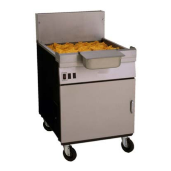
Models YSCFC 1824G, 2424G, and 24/24/15 Systems
with Built-In Filtration
Frymaster Dean, a member of the Commercial Food Equipment Service Association,
recommends using CFESA Certified Technicians.
24-Hour Service Hotline
PRINTED IN THE USA
FEBRUARY 2009
1-800-551-8633
*8196472*
service@frymaster.com
www.frymaster.com
Advertisement
Table of Contents
Troubleshooting

Subscribe to Our Youtube Channel
Related Manuals for Frymaster YSCFC24GSERIES YSCFC24GSERIES


Summary of Contents for Frymaster YSCFC24GSERIES YSCFC24GSERIES
- Page 1 Models YSCFC 1824G, 2424G, and 24/24/15 Systems with Built-In Filtration Frymaster Dean, a member of the Commercial Food Equipment Service Association, recommends using CFESA Certified Technicians. 24-Hour Service Hotline PRINTED IN THE USA FEBRUARY 2009 1-800-551-8633 *8196472* service@frymaster.com www.frymaster.com...
- Page 2 DIRECTLY FROM FRYMASTER DEAN, OR ANY OF ITS AUTHORIZED SERVICE CENTERS, AND/OR THE PART BEING USED IS MODIFIED FROM ITS ORIGINAL CONFIGURATION, THIS WARRANTY WILL BE VOID. FURTHER, FRYMASTER DEAN AND ITS AFFILIATES WILL NOT BE LIABLE FOR ANY CLAIMS, DAMAGES OR EXPENSES INCURRED BY THE CUSTOMER WHICH ARISE DIRECTLY OR INDIRECTLY, IN WHOLE OR IN PART, DUE TO THE INSTALLATION OF ANY MODIFIED PART AND/OR PART RECEIVED FROM AN UNAUTHORIZED SERVICE CENTER.
- Page 3 The front ledge of the fryer is not a step. Do not stand on the fryer. Serious injury can result Drawings and photos used in this manual are intended to illustrate operational, cleaning and technical procedures and may not conform to on-site management operational procedures.
-
Page 4: Table Of Contents
SERVICE PROCEDURES Functional Description Accessing Fryers for Servicing Cleaning Gas Valve Vent Tube Adjusting Burner Manifold Gas Pressure Calibrating the Thermatron Temperature Controller Replacing Fryer Components Remove/Replace Temperature Probe or High-Limit Thermostat 1.6.1 1.6.2 Removing/Replacing Rocker Switches 1.6.3 Replacing the Gas Valve 1.6.4... - Page 5 YSCFC Series Flatbottom Gas Fryers TABLE OF CONTENTS (cont.) PARTS LIST Blower Assembly, Combustion Air Burner Manifold and Related Components Flue Caps, Top Caps, and Related Components Cabinetry Door Assemblies and Component Parts Control Panels, Wireways, and Related Components Oil Return and Suction Manifold Filter Unit Frypot, Drain, and Oil Return Components 2.10...
-
Page 6: Chapter 1: Service Procedures
YSCFC SERIES FLATBOTTOM GAS FRYERS CHAPTER 1: SERVICE PROCEDURES 1.1 Functional Description YSCFC Series Flatbottom gas fryers contain a welded steel frypot (mild steel) with heat-transfer ducting on the frypot bottom for efficient heating of oil without scorching. A draft inducer draws air over the burners for combustion. - Page 7 YSCFC Series Flatbottom gas fryers are equipped with Thermatron temperature controller. The fryer is turned on and off by means of a rocker switch and the temperature is set by adjusting a potentiometer. The Thermatron board is located in the wireway box behind the control panel, or in a component box inside the cabinet (depending on fryer configuration).
-
Page 8: Accessing Fryers For Servicing
Frying systems with built-in filtration are equipped with drain microswitches that disable the fryer if the drain valves are not completely closed. Opening a drain valve (i.e. filtering or draining the fryer) automatically opens the reset switch circuit. The drain valve must be fully closed prior to resetting the safety switch. -
Page 9: Cleaning Gas Valve Vent Tube
4. Place the gas valve in the "ON" position then place the fryer power switch in the "ON" position. When the burner lights and continues to burn, note gas pressure reading for correct pressure in accordance with the table on page 1-1. -
Page 10: Calibrating The Thermatron Temperature Controller
2. Place the fryer ON/OFF switch in the "ON" position. Set the Thermatron dial to 325°F (162°C). 3. Allow the oil/shortening to stabilize at setpoint temperature. This is evident when the burners have cycled on and off several times. -
Page 11: Replacing Fryer Components
2. Allow the frypot to cool for 10 minutes before draining. Drain cooking oil/shortening from the frypot. Allow the frypot to cool completely before proceeding. 3. Remove the fryer door(s) for access to control panel screws. Lift door up, disengage rod from lower door bracket, and then remove door. (Current production models have spring-loaded door pins. - Page 12 YSCFC SERIES FLATBOTTOM GAS FRYERS CHAPTER 1: SERVICE PROCEDURES 8. Remove the sensor bulb guard to access the probe and high-limit (pictured above). Current production systems have a sensor bulb clamp that must be removed prior to removing the probe or high-limit from the frypot (pictured top right).
-
Page 13: Removing/Replacing Rocker Switches
1.6.2 Removing/Replacing Rocker Switches 1. Disconnect the fryer from the electrical supply. 2. The switches are located on a control box inside the unit. Remove the screws securing the front panel of the control box. Do not allow the panel to hang by the switch wiring harness wiring;... -
Page 14: Replacing The Gas Valve
1.6.3 Replacing the Gas Valve Drain the frypot or remove drain valve handle to prevent accidental opening before Disconnect fryer from electrical and gas supplies. Disconnect the wires from the gas valve terminal block, marking each wire to facilitate reconnections. -
Page 15: Removing/Replacing Blower Assembly Or Air Prover Switch
Multi-batteried systems after have upper and lower back panels, which must be removed to access the blower assembly. (fryer at left shown with upper back panel removed). After removing screws (arrows), remove blower assembly from firebox by pulling outward. -
Page 16: Replacing The Frypot
If not, and no further service to frypot/firebox is required, reverse the above steps to reassemble the fryer. ignition). Inspect frypot baffles through burner tube opening (arrow) for signs of burn-through or damage. - Page 17 YSCFC SERIES FLATBOTTOM GAS FRYERS CHAPTER 1: SERVICE PROCEDURES 1.6.6.2 Frypot/Firebox Removal/Replacement Procedure 1. Perform Procedure 1.6.5, Removing/Replacing Blower Assembly or Air Prover Switch, Steps 1 – 2. Disconnect the union at the gas valve. Remove four bolts connecting the burner manifold brackets to the burner box.
- Page 18 CHAPTER 1: SERVICE PROCEDURES 6. Remove two screws securing topcap to wireway box. Remove topcap. Remove four screws securing wireway box to fryer cabinet (arrows) and carefully lower wireway box out of the way. Use care not to stretch or distort the wiring.
- Page 19 YSCFC SERIES FLATBOTTOM GAS FRYERS CHAPTER 1: SERVICE PROCEDURES 10. Remove firebox back, insulation from back of frypot. From the rear of the unit, use a prying bar to carefully pry the top assembly from the frypot and cabinet frame (single units only), and set aside.
-
Page 20: Troubleshooting And Problem Isolation
(arrow). Reverse the above steps to reassemble the fryer. Use high-temp silicone to re-install the top assembly (single fryers) or joiner strips, flue caps, etc. (systems). 1.7 Troubleshooting and Problem Isolation This section is intended to provide technicians with a general knowledge of the broad problem categories associated with this equipment, and the probable causes of each. -
Page 21: Ignition Failures
Problems Related to the Electronic Circuits If gas and electrical power are supplied to the fryer, the next most likely cause of ignition failure is a problem in the 24 VAC circuit of electronic ignition systems. If the fryer is equipped with a filtration system, first verify that the drain valve is fully closed. -
Page 22: Improper Burner Functioning
If the fryer’s gas and air supplies are okay, the problem most likely is with one of the electrical components. Examine the ignition module for signs of melting/distortion and/or discoloration due to excessive heat build-up in the fryer. - Page 23 Check for proper operation by disconnecting the wire from the ignitor, inserting the tip of a screwdriver into the terminal, and holding it near the frame of the fryer as the power switch is placed in the "ON" position. A strong, blue spark should be generated for at least 11 seconds.
-
Page 24: Improper Temperature Control
Temperature control, including the melt cycle, is a function of several interrelated components, each of which must operate correctly. The principal component is the temperature probe. Depending upon the specific configuration of the fryer, other components may include the Thermatron board, the controller itself, and the ignition module. - Page 25 YSCFC SERIES FLATBOTTOM GAS FRYERS CHAPTER 1: SERVICE PROCEDURES A pump seized by debris or hard shortening must be disassembled, cleaned and reassembled as follows: 1. Disconnect power to the filter system. 2. Remove the front cover of the pump to access the gears inside, if the pump is accessible while still inside the cabinet.
-
Page 26: Leakage
YSCFC SERIES FLATBOTTOM GAS FRYERS CHAPTER 1: SERVICE PROCEDURES 1.7.5 Leakage Frypot leaks are usually due to improperly sealed high-limit, temperature probe or oil-return and drain fittings. When installed or replaced, each of these components must be sealed with Loctite PST567 sealant or equivalent to prevent leakage. -
Page 27: Troubleshooting Guides
(20 minutes). If problems with blower overheating persist, call for service. 3. If fryer is equipped with a Thermatron controller, the temperature probe or the controller board may be defective. 1. Check gas pressure at the pressure tap of the burner manifold. -
Page 28: Indicator Lights
The fryer’s indicator lights serve a diagnostic purpose. All lights are lit when the fryer is working properly. The green light on the control panel will cycle on and off as the fryer calls for heat. Use the following procedures to isolate problems indicated by light combinations. -
Page 29: Wiring Diagrams
YSCFC SERIES FLATBOTTOM GAS FRYERS CHAPTER 1: SERVICE PROCEDURES 1.9 WIRING DIAGRAMS NOTE: The diagrams in this section depict wiring as of the date of manual publication. It may not reflect design changes made to the equipment after publication. Always refer to the wiring diagram affixed to the unit when actually troubleshooting this equipment. -
Page 30: 24/24 Filter Wiring
YSCFC SERIES FLATBOTTOM GAS FRYERS CHAPTER 1: SERVICE PROCEDURES 1.9.2 24/24 Filter Wiring 1-25... -
Page 31: 18/24 Common Cabinet Transformer Box
YSCFC SERIES FLATBOTTOM GAS FRYERS CHAPTER 1: SERVICE PROCEDURES 1.9.3 18/24 Common Cabinet Transformer Box 1-26... -
Page 32: Chapter 2: Parts List
YSCFC SERIES FLATBOTTOM GAS FRYERS CHAPTER 2: PARTS LIST 2.1 Blower Assembly and Combustion Air ITEM PART # 108-0471SP Motor, Blower Assembly, 120V 823-3162 Duct Assembly, Inlet 200-1428 Gate, Air Flow 823-3166 Duct Assembly, Outlet 200-1471 Door, Outlet Duct Access * Not illustrated. -
Page 33: Burner Manifold And Related Components
YSCFC SERIES FLATBOTTOM GAS FRYERS CHAPTER 2: PARTS LIST 2.2 Burner Manifold and Related Components... - Page 34 YSCFC SERIES FLATBOTTOM GAS FRYERS 2.2 Burner Manifold and Related Components ITEM PART # 810-2129 Tube, Burner 200-1670 Support, Left or Right Manifold 810-2168 Burner Manifold Assembly Orifice 810-2827 2.82mm (#34) Natural Gas 810-2830 1.78mm (#50) Propane (LP) Gas 813-0154 Plug, ⅛"...
-
Page 35: Flue Caps, Top Caps, And Related Components
YSCFC SERIES FLATBOTTOM GAS FRYERS CHAPTER 2: PARTS LIST 2.3 Flue Caps, Top Caps, and Related Components... - Page 36 For use on 3-2424G (3-vat 2424 System) 210-4317 Edge Strip, Frypot 210-4313 Joiner Strip (joins frypots within a system) 210-4598 Joiner Strip (joins one fryer system to another) 230-3089 Joiner Strip (joins matching cabinet to fryer) Marine Edge 823-5640 2-vat 2424, Without Notches...
-
Page 37: Cabinetry
YSCFC SERIES FLATBOTTOM GAS FRYERS CHAPTER 2: PARTS LIST 2.4 Cabinetry... - Page 38 220-0760 Divider, Frypot 200-9231 Brace, Cabinet Front, 224 220-3793 Brace, Cabinet Front, 324 220-3501 Brace, Cabinet Front, 324, Filter on Right (facing the fryer) 200-9240 Brace, Cabinet Front, 1824 220-2970 Brace, Cabinet Front, 24/24/15 200-9229 Brace, Cabinet Top, 224 200-3793...
-
Page 39: Door Assemblies And Component Parts
YSCFC SERIES FLATBOTTOM GAS FRYERS 2.5 Door Assemblies and Component Parts ITEM PART # 824-1912 Panel, Door, 2424 824-1958 Panel, Door, 1824 824-1954 Panel, Door, MC15 220-4128 Liner, Door, 2424 220-4742 Liner, Door, 1824 220-4666 Liner, Door, MC15 106-4067 Pin Assembly 810-0275 Spring 210-8077... -
Page 40: Control Panels, Wireways, And Related Components
YSCFC SERIES FLATBOTTOM GAS FRYERS CHAPTER 2: PARTS LIST 2.6 Control Panels, Wireways, and Related Components... - Page 41 YSCFC SERIES FLATBOTTOM GAS FRYERS 2.6 Control Panels, Wireways, and Related Components ITEM PART # 106-6060 Plate, Microswitch Adjustment 807-4114 Relay, Latch/Filter 24VAC Coil 200-4719 Plate, Interface Board Mounting 200-9681 Support, High Limit Thermostat 200-9812 Plate, Component Box Cover 220-1283 Box, Component Harness 220-1284 Housing, Thermostat...
-
Page 42: Oil Return And Suction Manifold
YSCFC SERIES FLATBOTTOM GAS FRYERS CHAPTER 2: PARTS LIST 2.7 Oil Return and Suction Manifolds 2-11... - Page 43 YSCFC SERIES FLATBOTTOM GAS FRYERS 2.7 Oil Return and Suction Manifolds ITEM PART # 810-3088 Oil Return Manifold 106-5461 Oil Return Plumbing 810-2125 Drain Valve, ⅜" Ball Valve 810-3011 Tubing, Drain Valve, Front 810-3014 Tubing, Oil Return, Rear 813-0165 Elbow, Street, ½" x ½" NPT, 90° 813-0462 Coupling, ⅜"...
-
Page 44: Filter Unit
YSCFC SERIES FLATBOTTOM GAS FRYERS 2.8 Filter Unit ITEM PART # 106-8465SP Filter Pan (with 2" casters) 810-2800 Filter Leaf 823-5833 Crumb Basket 106-6131 Lid, Filter Pan 810-2805 Caster, 2" 826-1392 O-rings (for filter pan pick up tube; qty. 5) 816-0757 O-rings (for filter leaf) 803-0342... -
Page 45: Frypot, Drain, And Oil Return Components
YSCFC SERIES FLATBOTTOM GAS FRYERS CHAPTER 2: PARTS LIST 2.9 Frypot, Drain, and Oil Return Components 2-14... - Page 46 YSCFC SERIES FLATBOTTOM GAS FRYERS 2.9 Frypot, Drain, and Oil Return Components ITEM PART # 826-1823 Frypot Kit, 1824G (insulation included) 826-1821 Frypot Kit, 2424G (insulation included) 823-3934 Divider, Frypot 823-3174 Plug, Frypot Drain 823-3190 Baffle, Secondary Air 210-1409 Spreader, Side Flame Firebox Assembly 823-5854 1824 (use with 823-5195 on 1824 units)
-
Page 47: Drain Valve And Components
YSCFC SERIES FLATBOTTOM GAS FRYERS 2.10 Drain Valve and Components ITEM PART # 810-2867 Valve, Drain 1¼" (1" Std. Port) 200-8867 Strap, 3" Drain 106-6020 Bracket Assembly 816-0220 Insulation 807-2103 Switch, Micro CE Straight Lever 220-3517 Cover, Safety Switch 826-1366 Nut, 4-40 Keps Hex (Pkg. -
Page 48: Wiring Connectors, Pin Terminals, And Power Cords
YSCFC SERIES FLATBOTTOM GAS FRYERS 2.11 Wiring Connectors, Pin Terminals, and Power Cords ITEM PART # 106-7649 Power Cord Assembly 120V 10’ 16 gauge Connectors 807-1068 2-Pin Female 807-0158 6-Pin Female 807-0156 9-Pin Female 807-0159 12-Pin Female 807-0875 15-Pin Female 807-1067 2-Pin Male 807-0157... - Page 49 YSCFC SERIES FLATBOTTOM GAS FRYERS 2.12 Screws, Nuts, and Fasteners ITEM PART # 826-1389 Screw, ¼-20 x ¾" (Pkg. of 10) 826-1359 Screw, 4-40 x ¾" Slotted Round Head (Pkg. of 25) 809-0853 Screw, 10-32 x 1.5" Slotted Pan Head 809-0839 Screw, 8-32 x .75"...
-
Page 50: Service Hotline
Frymaster/Dean, 8700 Line Avenue, Shreveport, Louisiana 71106 TEL 1-318-865-1711 FAX (Parts) 1-318-688-2220 FAX (Tech Support) 1-318-219-7135 SERVICE HOTLINE 819-6472 PRINTED IN THE UNITED STATES FEB 2009 1-800-551-8633...
Need help?
Do you have a question about the YSCFC24GSERIES YSCFC24GSERIES and is the answer not in the manual?
Questions and answers