
Subscribe to Our Youtube Channel
Related Manuals for Planet IGS-501T


Summary of Contents for Planet IGS-501T
- Page 1 5-/8-Port 10/100/1000Mbps Industrial Gigabit Ethernet Switch IGS-501T/IGS-801T User's Manual...
-
Page 2: Table Of Contents
Table of Contents 1. Package Contents ..............3 2. Hardware Introduction ............... 4 2.1 Physical Dimensions ............4 2.2 Switch Front Panel .............. 6 2.3 LED Indicators ..............7 2.4 Switch Upper Panel ............. 8 2.5 Wiring the Power Inputs ............8 2.6 Wiring the Fault Alarm Contact .......... -
Page 3: Package Contents
1. Package Contents Thank you for purchasing PLANET 5-/8-Port 10/100/1000T industrial Gigabit Ethernet Switch, IGS-501T and IGS-801T. In the following section, the term “Industrial Gigabit Ethernet Switch” means the IGT-501T/IGT-801T. Open the box of the Industrial Gigabit Ethernet Switch and carefully unpack it. -
Page 4: Hardware Introduction
2. Hardware Introduction 2.1 Physical Dimensions IGS-501T dimensions (W x D x H): 135 x 87 x 32mm Rear View 53.50 53.50 18.00 Top View 46.50 48.80 39.70 97.10 87.80 Side View Front View 87.80 9.20 135.00 15.20 32.00 30.00... - Page 5 IGS-801T dimensions (W x D x H): 135 x 87 x 32mm Rear View Top View Side View Front View V1+ V1- V2+ V2- Input PWR1 Fault PWR2 DC12~48V, AC 24V Bottom View Dimensions ( unit = mm )
-
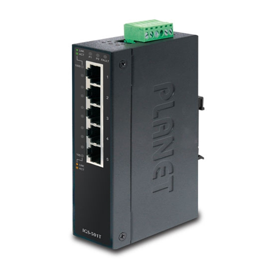
Page 6: Switch Front Panel
Indicators are also located on the RJ45 ports of the Gigabit Ethernet Switch. Figures 2-1 and 2-2 show the front panels of Industrial Gigabit Ethernet Switches. P2 FAULT 1000 IGS-801T Figure 2-1: IGS-501T Front Panel Figure 2-2: IGS-801T Front Panel... -
Page 7: Led Indicators
2.3 LED Indicators IGS-501T: Color Function Green Lit: indicates power 1 has power. Green Lit: indicates power 2 has power. Lit: indicates either power 1 or power 2 has no power. FAULT Green Lit: indicates the port is successfully connecting to the network at 1000Mbps. -
Page 8: Switch Upper Panel
2.4 Switch Upper Panel The upper panel of the Industrial Gigabit Ethernet Switch consists of one terminal block connector within two DC power inputs. Figure 2-3 shows the upper panel of the Industrial Gigabit Ethernet Switch. Figure 2-3: Industrial Gigabit Ethernet Switch Upper Panel 2.5 Wiring the Power Inputs The 6-contact terminal block connector on the top panel of Industrial Gigabit Ethernet Switch is used for two DC redundant power inputs. -
Page 9: Wiring The Fault Alarm Contact
2. Tighten the wire-clamp screws for preventing the wires from loos- ening. Power 1 Fault Power 2 1 The wire gauge for the terminal block should be in the range between 12 and 24 AWG. 2. The device must be grounded. Note 3. -
Page 10: Product Specifications
The Fault Alarm Contacts are energized (CLOSE) for normal operation and will OPEN when Fault Alarm Contacts Fault failure occurs 2.7 Product Specifications Model IGS-501T IGS-801T Hardware Specifications 10/100/1000BASE-T Ports Dimensions 135 x 87 x 32 mm (W x D x H) - Page 11 Address Table 1.5Mbits SRAM packet Buffer 1M bits buffer Back pressure for half duplex Flow Control IEEE 802.3x pause frame for full duplex Switch Fabric 10Gbps 16Gbps Throughput 7.4Mpps 11.9Mpps (packet per second) Jumbo Frame 10/100/1000BASE-T: Network Cables Cat3, 4, 5, 5e, 6 UTP cable (100 meters, max.) EIA/TIA-568 100-ohm STP (100 meters, max.) Standards Conformance IEEE 802.3 Ethernet...
-
Page 12: Installation
3. Installation 3.1 DIN-rail Mounting Installation The DIN-rail is screwed on the Industrial Gigabit Ethernet Switch when out of factory. When you need to replace the wall-mount application with DIN-rail application on Industrial Gigabit Ethernet Switch, please refer to the following figures to screw the DIN-rail on the Industrial Gigabit Ethernet Switch. - Page 13 Step 3: Check whether the DIN-rail is tightly on the track. Step 4: Please refer to the following procedure to remove the Industrial Gigabit Ethernet Switch from the track. Step 5: Lightly pull out the bottom of DIN-rail to remove it from the track.
-
Page 14: Wall-Mount Plate Mounting
3.2 Wall-mount Plate Mounting To install the Industrial Gigabit Ethernet Switch on the wall, please follow the instructions described below. Step 1: Remove the DIN-rail from the Industrial Gigabit Ethernet Switch; loosen the screws to remove the DIN-rail. Step 2: Place the wall-mount plate on the rear panel of the Industrial Gigabit Ethernet Switch. -
Page 15: Troubleshooting
4. Troubleshooting This chapter contains information to help you solve issues. If the Industrial Gigabit Ethernet Switch is not functioning properly, make sure the Industrial Gigabit Ethernet Switch was set up according to instructions in this manual. The per port LED is not lit Solution: Check the cable connection of the Industrial Gigabit Ethernet Switch. -
Page 16: Customer Support
5. Customer Support Thank you for purchasing PLANET products. You can browse our online FAQ resource and User’s Manual on PLANET Web site first to check if it could solve your issue. If you need more support information, please contact PLANET switch support team. -
Page 17: Appendix A: Networking Connection
APPENDIX A: Networking Connection A.1 Switch’s RJ45 Pin Assignments 1000Mbps, 1000BASE-T Contact MDI-X BI_DA+ BI_DB+ BI_DA- BI_DB- BI_DB+ BI_DA+ BI_DC+ BI_DD+ BI_DC- BI_DD- BI_DB- BI_DA- BI_DD+ BI_DC+ BI_DD- BI_DC- 10/100Mbps, 10/100BASE-TX RJ45 Connector pin assignment MDI-X Contact Media Dependent Media Dependent Interface Interface-Cross Tx + (transmit) -
Page 18: Rj45 Cable Pin Assignments
A.2 RJ45 Cable Pin Assignments The standard RJ45 receptacle/connector There are 8 wires on a standard UTP/STP cable and each wire is color- coded. The following shows the pin allocation and color of straight- through cable and crossover cable connection: Straight Cable SIDE 1 SIDE 2... -
Page 19: Ec Declaration Of Conformity
EC Declaration of Conformity For the following equipment: *Type of Product : 5-/8-Port 10/100/1000Mbps Industrial Ethernet Switch *Model Number : IGS-501T, IGS-801T * Produced by: Manufacturer‘s Name : Planet Technology Corp. Manufacturer‘s Address : 10F., No.96, Minquan Rd., Xindian Dist., New Taipei City 231, Taiwan (R.O.C.)
Need help?
Do you have a question about the IGS-501T and is the answer not in the manual?
Questions and answers