Table of Contents
Advertisement
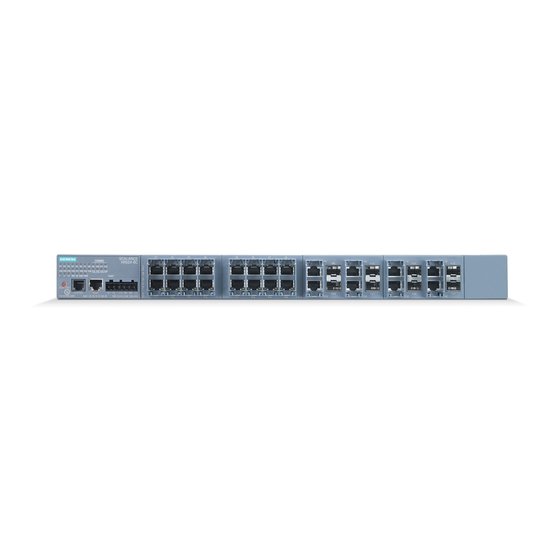
SIMATIC NET
Industrial Ethernet switches
SCALANCE XR-500
Operating Instructions
05/2017
A5E03275845-11
___________________
Introduction
___________________
Safety notes
___________________
Description of the device
___________________
Assembling
___________________
Connecting
___________________
Uninstalling
___________________
Upkeep and maintenance
Technical data
___________________
Dimension drawings
___________________
Certification
1
2
3
4
5
6
7
8
9
10
Advertisement
Table of Contents


Need help?
Do you have a question about the SCALANCE XR524-8C and is the answer not in the manual?
Questions and answers