Table of Contents
Advertisement
Quick Links
SIMATIC NET
Industrial Ethernet Switches
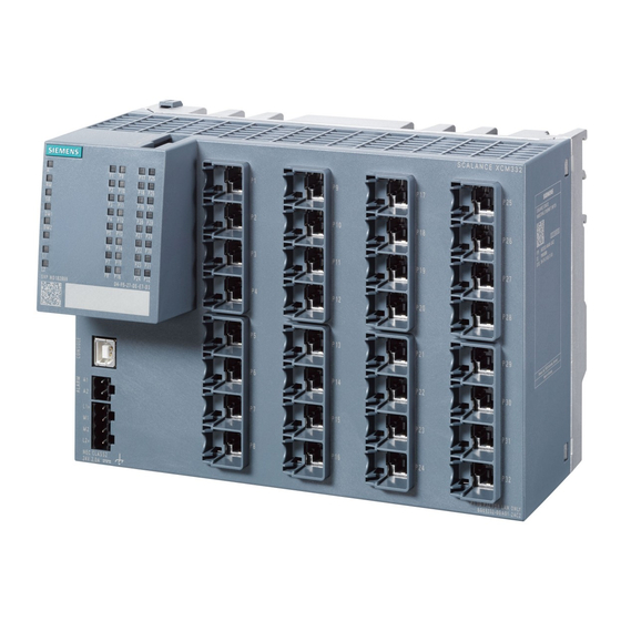
SCALANCE XCM-300
Product Manual
04/2022
C79000-G8976-C585-01
Introduction
Safety notices
Recommendations on
network security
Description of the device
installing and removing
Connecting up
Maintenance and cleaning
Troubleshooting
Technical specifications
Dimension drawings
Certifications and approvals
1
2
3
4
5
6
7
8
9
10
11
Advertisement
Table of Contents

Related Manuals for Siemens SIMATIC NET SCALANCE XCM-300


Summary of Contents for Siemens SIMATIC NET SCALANCE XCM-300
- Page 1 Introduction Safety notices Recommendations on network security SIMATIC NET Description of the device Industrial Ethernet Switches SCALANCE XCM-300 installing and removing Connecting up Product Manual Maintenance and cleaning Troubleshooting Technical specifications Dimension drawings Certifications and approvals 04/2022 C79000-G8976-C585-01...
- Page 2 Note the following: WARNING Siemens products may only be used for the applications described in the catalog and in the relevant technical documentation. If products and components from other manufacturers are used, these must be recommended or approved by Siemens. Proper transport, storage, installation, assembly, commissioning, operation and maintenance are required to ensure that the products operate safely and without any problems.
-
Page 3: Table Of Contents
Table of contents Introduction ............................7 Scope of validity ........................7 Designations used........................ 7 Supplementary documentation.................... 7 SIMATIC NET glossary......................9 Security information ......................9 Error/fault ..........................9 Decommissioning ........................ 9 Recycling and disposal ....................... 10 Trademarks........................10 1.10 Electrostatic discharge ....................... 10 Safety notices ............................ - Page 4 Table of contents Configuration and License PLUG ..................28 4.8.1 Position ..........................28 4.8.2 Function ..........................29 Function extender interface for the SCALANCE LPE ............. 29 installing and removing........................31 Safety during mounting ..................... 31 Types of installation ......................34 Mounting on DIN rails ......................
- Page 5 Table of contents Dimension drawings ..........................67 10.1 Dimension drawings SCALANCE XCM-300 ................67 10.2 SCALANCE LPE9403 dimension drawings ................69 Certifications and approvals ........................ 73 Index ..............................81 SCALANCE XCM-300 Product Manual, 04/2022, C79000-G8976-C585-01...
- Page 6 Table of contents SCALANCE XCM-300 Product Manual, 04/2022, C79000-G8976-C585-01...
-
Page 7: Introduction
The listed documents are the documents that were available at the time of the publication. Newer versions of these documents or the associated products may be available. Additional information is available in the SIOS or contact your Siemens customer service. SCALANCE XCM-300... - Page 8 There, you will find among other things optical performance data of the communication partners that you require for the design. Catalogs You will find the article numbers for the Siemens products of relevance here in the following catalogs: • SIMATIC NET Industrial Communication / Industrial Identification, catalog IK PI •...
-
Page 9: Simatic Net Glossary
To stay informed about product updates, subscribe to the Siemens Industrial Security RSS Feed under https://www.siemens.com/cert (https://www.siemens.com/cert). Error/fault If a fault develops, send the device to your SIEMENS representative for repair. Repairs on-site are not possible. Decommissioning Shut down the device properly to prevent unauthorized persons from accessing confidential data in the device memory. -
Page 10: Recycling And Disposal
2012/19/EU for the disposal of electrical and electronic equipment. Do not dispose of the products at public disposal sites. For environmentally friendly recycling and the disposal of your old device contact a certified disposal company for electronic scrap or your Siemens contact (Product return (https:// support.industry.siemens.com/cs/ww/en/view/109479891)). -
Page 11: Safety Notices
Safety notices Read the safety notices Note the following safety notices. These relate to the entire working life of the device. You should also read the safety notices relating to handling in the individual sections, particularly in the sections "Installation" and "Connecting up". CAUTION To prevent injury and damage, read the manual before using the device. - Page 12 Safety notices SCALANCE XCM-300 Product Manual, 04/2022, C79000-G8976-C585-01...
-
Page 13: Recommendations On Network Security
For more information, visit Industrial Security Website (https://www.siemens.com/ industrialsecurity). • Review the user documentation for other Siemens products used along with the device for further security recommendations. • Use remote system logging to forward system logs to a central logging server. Make sure the server is within the protected network and check the logs regularly to identify potential security breaches/vulnerabilities. - Page 14 • Use password-protected certificates that are in PKCS #12 format. • Use certificates with a key length of 4096 bits. • Before returning the device to Siemens for repair, replace the current certificates and keys with temporary throwaway certificates and keys that can be destroyed upon the device's return.
- Page 15 Recommendations on network security 3.1 Security recommendations • Terminate management connections (e.g. HTTP, HTTPS, SSH, etc.) properly. • Make sure the device is fully decommissioned before taking the device out of service. For more information, refer to "Supplementary documentation (Page 7)". Secure/non-secure protocols •...
-
Page 16: Available Services
For the latest information on security patches for Siemens products, visit the Industrial Security (https://www.siemens.com/industrialsecurity) website or the ProductCert Security Advisories (https://www.siemens.com/cert/en/cert-security-advisories.htm) website. Updates to the Siemens Product Security Advisories can be obtained by subscribing to the RSS feed on the Siemens ProductCERT Security Advisories website, or by following @ProductCert on Twitter. - Page 17 Recommendations on network security 3.2 Available services • Authentication Specifies whether an authentication of the communication partner takes place or whether an authentication can be configured. • Encryption Specifies whether the transfer is encrypted or whether the encryption is configurable. Service Protocol Port num‐...
- Page 18 Recommendations on network security 3.2 Available services SCALANCE XCM-300 Product Manual, 04/2022, C79000-G8976-C585-01...
-
Page 19: Description Of The Device
Description of the device Article numbers Device Description Article number SCALANCE XCM332 6GK5332-0GA01-2AC2 • 32 x 10 / 100 / 1000 Mbps RJ45 ports • 2 x 2-pin terminal block 24 V DC, power supply connection • 1 x CLP slot •... -
Page 20: Device Views
Description of the device 4.2 Device views Device views 4.2.1 Device view of a SCALANCE XCM332 The following figure shows an overview of the components of the SCALANCE XCM332: ① ⑪ Port LEDs "SELECT/SET" button ② ⑫ CLP slot Function extender interface for the SCALANCE ③... -
Page 21: Components Of The Product
Description of the device 4.4 Spare parts Components of the product The following components are supplied with a SCALANCE XCM-300: • One SCALANCE XCM-300 • One CLP removable data storage medium 2 GB – For a SCALANCE XCM-300 without conformal-coated PCBs: Article number 6GK1900-0UB00-0AA0 •... -
Page 22: Accessories
Description of the device 4.5 Accessories Accessories The following accessories are available for the devices mentioned in the scope of validity: 4.5.1 Configuration and License PLUG Component Description Article number SCALANCE CLP 2 GB Configuration and License PLUG, remova‐ 6GK1900-0UB00-0AA0 ble data storage medium for configuration data, 2 GB SCALANCE CLP EEC 2 GB... - Page 23 Description of the device 4.5 Accessories Device Description Article number SCALANCE LPE9403 The SCALANCE LPE can be operated either standalone or con‐ 6GK5 998-3GS00-2AC2 nected with a SCALANCE XCM-300. In standalone operation, the SCALANCE LPE has the following ports: • 2 x 10/100/1000 Mbps RJ45 ports •...
-
Page 24: Led Display
Description of the device 4.6 LED display LED display 4.6.1 Position The following figure shows the arrangement of the LEDs using the example of a SCALANCE XCM332. LED for displaying the alarm status LED without function LED without function DM1/DM2 LEDs for displaying the display mode L1/L2 LEDs for displaying the power supply... -
Page 25: Leds "Dm1" And "Dm2
Description of the device 4.6 LED display Meaning during operation LED color LED status Meaning during operation The device is operating free of errors. The device has detected a problem. 4.6.3 LEDs "DM1" and "DM2" The "DM1" and "DM2" LEDs indicate which display mode is set. There are 4 display modes (A, B, C and D). - Page 26 Description of the device 4.6 LED display Meaning in display mode A In display mode A, the port LEDs indicate whether a valid link exists. LED color LED status Meaning No valid link on the port (e.g. the communication partner is switched off or the cable is not connected) or the link is present but the port is switched off by management.
-
Page 27: Select/Set Button
Description of the device 4.7 SELECT/SET button SELECT/SET button 4.7.1 Position The "SELECT/SET" button is located on the front of the device. Figure 4-3 Position of the "SELECT/SET" button using the example of a SCALANCE XCM332 4.7.2 Function The device has a button with the following functions: •... -
Page 28: Setting The Display Mode
The CLP has a USB type C interface and can be used with the following devices that have a corresponding interface: • Siemens products • Personal computers (PCs), such as desktop PCs, tablet PCs, laptops, or smartphones 4.8.1 Position The CLP slot is located on the top of the device. -
Page 29: Function
– The configuration data of the device is stored in a secured memory area of the CLP. This secured memory area can only be accessed via the authentication of the Siemens device. – The device checks whether a CLP is inserted at one second intervals. If the device detects that the CLP has been removed, it restarts automatically. - Page 30 In addition, applications that take on important functions in the plant, for example network services such as DHCP or NTP, can run directly on the SCALANCE LPE. For more information, refer to the SCALANCE LPE (https://mall.industry.siemens.com/ mall/en/WW/Catalog/Products/10399441?tree=CatalogTree) product information. SCALANCE XCM-300...
-
Page 31: Installing And Removing
installing and removing Safety during mounting Safety notices When installing the device, keep to the safety notices listed below. WARNING If a device is operated in an ambient temperature of more than 55 °C, the temperature of the device enclosure may be higher than 70 °C. The device must therefore be installed so that it is only accessible to service personnel or users that are aware of the reason for restricted access and of the required safety measures at an ambient temperature higher than 55 to 70 °C. - Page 32 installing and removing 5.1 Safety during mounting Safety notices on use in hazardous areas General safety notices relating to protection against explosion WARNING EXPLOSION HAZARD Replacing components may impair suitability for Class 1, Division 2 or Zone 2. WARNING The device is intended for indoor use only. WARNING The device may only be operated in an environment of contamination class 1 or 2 (see EN/IEC 60664-1, GB/T 16935.1).
- Page 33 installing and removing 5.1 Safety during mounting WARNING EXPLOSION HAZARD For operation the device is intended to be installed within an enclosure/control cabinet. The inner temperature of the enclosure/control cabinet corresponds to the ambient temperature of the device. Use cables with a permitted operating temperature of at least 90 °C. WARNING Wall mounting outside of the control cabinet or housing does not fulfill the requirements of the FM approval.
-
Page 34: Types Of Installation
installing and removing 5.2 Types of installation Further notes NOTICE Warming and premature aging of the network component due to direct sunlight Direct sunlight can heat up the device and can lead to premature aging of the network component and its cabling. Provide suitable shade to protect the network component against direct sunlight. -
Page 35: Mounting On Din Rails
installing and removing 5.3 Mounting on DIN rails The following installation positions are permitted, but with deviating temperature values (Page 63): • Vertical (position 2) Vertical installation of the rack (DIN rail/mounting rail) Figure 5-2 Vertical installation position of a SCALANCE XCM-300 on a DIN rail •... -
Page 36: Installation On A Standard S7-300 Rail
installing and removing 5.4 Installation on a standard S7-300 rail Figure 5-3 DIN rail mounting with securing bar in the wall mounting position. Securing bar in the wall mounting position (as supplied). To install the device on a 35 mm DIN rail complying with DIN EN 60715, follow the steps below: 1. - Page 37 installing and removing 5.4 Installation on a standard S7-300 rail Figure 5-4 S7-300 mounting rail installation with the securing bar in the wall mounting position. Securing bar in the wall mounting position (as supplied). To install the device on an S7-300 standard rail, follow the steps below: 1.
-
Page 38: Installation On A Standard S7-1500 Rail
installing and removing 5.5 Installation on a standard S7-1500 rail Installation on a standard S7-1500 rail Installing on an S7-1500 standard rail Note Note the position of the securing bar, see also section “Dimension drawings (Page 67)“. When supplied, the securing bar is in the wall mounting position. To change the position of the securing bar, refer to the section “Changing the position of the securing bar (Page 40)“. -
Page 39: Wall Mounting
installing and removing 5.6 Wall mounting Wall mounting Preparation Note the position of the securing bar, see also section “Dimension drawings (Page 67)“. When supplied, the securing bar is in the wall mounting position. You do not need to prepare the device any further. -
Page 40: Changing The Position Of The Securing Bar
installing and removing 5.7 Changing the position of the securing bar Changing the position of the securing bar Rail mounting position - wall mounting position To change the securing bar from the rail mounting position to the wall mounting position follow the steps below: 1. -
Page 41: Connecting A Scalance Xcm-300 With A Scalance Lpe
installing and removing 5.8 Connecting a SCALANCE XCM-300 with a SCALANCE LPE Connecting a SCALANCE XCM-300 with a SCALANCE LPE Position The following figure shows the elements required to connect a SCALANCE XCM-300 with a SCALANCE LPE. ① Lock (on the device rear of the SCALANCE XCM-300) ②... -
Page 42: Disassembly
installing and removing 5.9 Disassembly Follow these steps to connect a SCALANCE XCM-300 with a SCALANCE LPE: 1. Disconnect the two devices from the power supply. 2. Remove the function extender interface cover on the SCALANCE XCM-300. 3. Remove the connector cover on the SCALANCE LPE. ②... -
Page 43: Connecting Up
Connecting up Safety when connecting up Safety notices for operation with a power supply according to NEC Class 2 Operate the device with a power supply according to NEC Class 2. When connecting up the device, keep to the safety notices listed below. WARNING Power supply The device is designed for operation with a directly connectable safety extra low voltage (SELV) - Page 44 Connecting up 6.1 Safety when connecting up NOTICE Suitable fuse for the power supply cables (corresponds to "Limited Energy") The current on the terminal may not exceed 3 A. Use a fuse for the power supply that is suitable for protection of AC/DC power supply circuits * and protects against currents >...
- Page 45 Connecting up 6.1 Safety when connecting up WARNING Power supply The device is designed for operation with a directly connectable safety extra-low voltage (Safety Extra Low Voltage, SELV) according to UL/IEC 61010‑1 and UL/IEC 61010‑2‑201. Further notes WARNING Insulation of external power supplies Ext.
- Page 46 Connecting up 6.1 Safety when connecting up Safety notices on use in hazardous areas General safety notices relating to protection against explosion WARNING EXPLOSION HAZARD Do not connect or disconnect cables to or from the device when a flammable or combustible atmosphere is present.
- Page 47 Connecting up 6.1 Safety when connecting up WARNING Improper installation of shielded cables There is a risk of explosion due to equalizing currents between the hazardous area and the non- hazardous area. • Ground shielded cables that cross hazardous areas at one end only. •...
-
Page 48: Wiring Rules
Connecting up 6.2 Wiring rules WARNING EXPLOSION HAZARD You may only connect or disconnect cables carrying electricity when the power supply is switched off or when the device is in an area without inflammable gas concentrations. Safety notices when using according to FM If you use the device under FM conditions you must also keep to the following safety notices in addition to the general safety notices for protection against explosion: WARNING... -
Page 49: Power Supply
Connecting up 6.3 Power supply Power supply Notes on the power supply WARNING Incorrect power supply When the device is connected to a redundant power supply (two separate power supplies), both must meet these requirements. Never operate the device with AC voltage or DC voltage higher than 32 V DC. CAUTION Damage to the device due to overvoltage The connector of the external power supply is not protected against strong electromagnetic... -
Page 50: Functional Ground
Connecting up 6.4 Functional ground Position and assignment Figure 6-1 Position of the power supply based on the example of a SCALANCE XCM332 and assignment of the terminal block Contact Assignment 24 V DC Ground Ground 24 V DC Functional ground EMC disturbances are diverted to ground via the functional ground. -
Page 51: Industrial Ethernet
Connecting up 6.5 Industrial Ethernet ① Grounding terminal with cable ② Fillister head screw with spring washer and washer 1. Loosen the grounding screw). 2. Put the grounding terminal and grounding screw together. 3. Tighten the grounding screw with a maximum torque of 0.75 Nm. Protective/functional ground The connection of the reference potential surface with the protective ground system is normally in the cabinet close to the power feed-in. - Page 52 Unlocking the plug with a screwdriver If installation space is limited, you can unlock the connectors using a screwdriver, see also "SIMATIC NET: IE FC RJ45 Plug 4x2 CAT 6A (https://support.industry.siemens.com/cs/ww/en/ view/102047916)". R-45 connector technology The attachment to Industrial Ethernet uses RJ-45 connected technology with MDI-X assignment.
-
Page 53: Signaling Contact
Connecting up 6.6 Signaling contact Autonegotiation Autonegotiation means the automatic detection/negotiation of the transmission rate and the operating mode of ports at the opposite end. This makes it possible to configure different devices automatically. Two components connected to a link segment can exchange information about the transfer and can adapt their settings to each other. -
Page 54: Usb Console Interface
Connecting up 6.7 USB console interface NOTICE Damage due to voltage being too high You can load the signaling contact with the operating voltage of the device and a maximum of 100 mA. Higher voltages or currents can damage the device. Position and assignment Figure 6-2 Position of the signaling contact based on the example of a SCALANCE XCM332 and... -
Page 55: Replacing A Clp
6.8 Replacing a CLP Driver for the USB console interface To use the USB console interface under Windows, you must download and install the following driver: Drivers (https://support.industry.siemens.com/cs/ww/en/ps/6GK5998-3GS00-2AC2/dl). Position Figure 6-3 Position of the USB console interface (USB socket type B) using the example of a SCALANCE... - Page 56 Connecting up 6.8 Replacing a CLP Removing a CLP To remove a CLP from the device, follow the steps below: 1. Turn off the power to the device. ② 2. To release the CLP, insert a screwdriver between the front edge of the CLP and the slot.
-
Page 57: Maintenance And Cleaning
Maintenance and cleaning WARNING Unauthorized repair of devices in explosion-proof design Risk of explosion in hazardous areas • Repair work may only be performed by personnel authorized by Siemens. WARNING Impermissible accessories and spare parts Risk of explosion in hazardous areas •... - Page 58 Maintenance and cleaning SCALANCE XCM-300 Product Manual, 04/2022, C79000-G8976-C585-01...
-
Page 59: Troubleshooting
Troubleshooting Resetting the device to default settings with the button (in the startup phase) NOTICE Connection hazard - risk of communication failure Depending on the configuration of your network, a reset device can cause circular frames and thus the loss of data traffic. NOTICE Configuration hazard - risk of data loss If a CLP is inserted in the device, the CLP is also reset to default settings. -
Page 60: Resetting The Device To Default Settings With The Button (During Operation)
Troubleshooting 8.2 Resetting the device to default settings with the button (during operation) Resetting the device to default settings with the button (during operation) NOTICE Connection hazard - risk of communication failure Depending on the configuration of your network, a reset device can cause circular frames and thus the loss of data traffic. -
Page 61: Loading A Firmware File Via Tftp
The device restarts with default settings. Loading a firmware file via TFTP Firmware The firmware is signed and encrypted. This ensures that only firmware created by Siemens can be downloaded to the device. Procedure with Microsoft Windows You can download new firmware to the device using TFTP. For this, the device cannot be accessible via the Web User Interface (Web UI) or via the Command Line Interface (CLI). - Page 62 Troubleshooting 8.3 Loading a firmware file via TFTP 5. Connect a client PC to an Ethernet port of the device via an Ethernet cable. NOTICE Risk of communication failure Ensure that only this one Ethernet cable is connected to the switch. Plugging in multiple Ethernet cables can cause communication failure.
-
Page 63: Technical Specifications
Load rating Max. 100 mA Button Quantity Configuration interface Removable data storage medium Quantity Product name Siemens Configuration and License PLUG (CLP) Function extender interface (SCALANCE LPE) Quantity Ethernet interfaces • 2 x 1 Gbps • 1 x 10 Gbps... - Page 64 Technical specifications 9.1 Technical specifications of SCALANCE XCM332 Technical specifications Effective power loss DC rated voltage With connected 62.4 W Without LPE 43.2 W Cable cross-section Minimum 0.75 mm (AWG 18) Maximum 2.5 mm (AWG 12) Permitted ambient conditions Ambient temperature With operation up to 2000 m above During operation in horizontal installation po‐...
-
Page 65: Mechanical Stability (In Operation)
Technical specifications 9.4 Switching properties Mechanical stability (in operation) The devices listed in the scope of validity meet the following requirements for mechanical stability during operation: IEC 60068-2-27 shock IEC 60068-2-6 vibration • 15 g, 11 ms duration • 10 - 58 Hz: 0.075 mm •... -
Page 66: Rf Radiation According To Namur Ne21
Technical specifications 9.5 RF radiation according to NAMUR NE21 Switching properties Full wire speed switching Frame length (bytes) Number of frames per second At 100 Mbps At 1000 Mbps With 10 Gbps 148810 1488095 14880952 84459 844595 8445946 45290 452899 4528986 23496 234962... -
Page 67: Dimension Drawings
Dimension drawings 10.1 Dimension drawings SCALANCE XCM-300 Note Dimensions are specified in mm. Front view This front view applies to all SCALANCE XCM-300 devices. ① Securing bar in the rail mounting position ② Securing bar in the wall mounting position (as supplied). SCALANCE XCM-300 Product Manual, 04/2022, C79000-G8976-C585-01... - Page 68 Dimension drawings 10.1 Dimension drawings SCALANCE XCM-300 Side view This side view applies to all SCALANCE XCM-300. ① Securing bar in the rail mounting position ② Securing bar in the wall mounting position (as supplied). SCALANCE XCM-300 Product Manual, 04/2022, C79000-G8976-C585-01...
-
Page 69: Scalance Lpe9403 Dimension Drawings
Dimension drawings 10.2 SCALANCE LPE9403 dimension drawings Drilling template for wall mounting The drilling pattern applies to all SCALANCE XCM-300 devices. 10.2 SCALANCE LPE9403 dimension drawings Note Dimensions are specified in mm. SCALANCE XCM-300 Product Manual, 04/2022, C79000-G8976-C585-01... - Page 70 Dimension drawings 10.2 SCALANCE LPE9403 dimension drawings Front view SIEMENS ① Securing bar in the rail mounting position ② Securing bar in the wall mounting position (as supplied) SCALANCE XCM-300 Product Manual, 04/2022, C79000-G8976-C585-01...
- Page 71 Dimension drawings 10.2 SCALANCE LPE9403 dimension drawings Side view SCALANCE XCM-300 Product Manual, 04/2022, C79000-G8976-C585-01...
- Page 72 Dimension drawings 10.2 SCALANCE LPE9403 dimension drawings Drilling template for wall mounting ‡ SCALANCE XCM-300 Product Manual, 04/2022, C79000-G8976-C585-01...
-
Page 73: Certifications And Approvals
Current approvals on the Internet You will find the current approvals for the product on the Internet pages of Siemens Industry Online Support (https://support.industry.siemens.com/cs/ww/en/ps/15273/cert). Notes for the manufacturers of machines This product is not a machine in the sense of the EC Machinery Directive or the Supply of Machinery (Safety) Regulations (UK). - Page 74 Process Automation DE-76181 Karlsruhe Germany Importer UK: Siemens plc, Manchester M20 2UR You can find the current UK Declaration of Conformity for these products on the Internet pages under Siemens Industry Online Support (https://support.industry.siemens.com/cs/ww/en/ps/ 15273/cert). SCALANCE XCM-300 Product Manual, 04/2022, C79000-G8976-C585-01...
- Page 75 "SIMATIC NET Product Information Use of subassemblies/modules in a Zone 2 Hazardous Area". You will find this document • on the data medium that ships with some devices. • on the Internet pages under Siemens Industry Online Support (https:// support.industry.siemens.com/cs/ww/en/view/78381013).
- Page 76 Certifications and approvals You will find the current versions of the standards in the currently valid certificates. Note for devices with CLASS 1 LASER Important note on products certified according to Type Examination Certificate KEMA 07ATEX0145 X as of Issue 95 / DEKRA 18ATEX0025 X and IECEx Certificate of Conformity DEK 14.0025X as of Issue 43 / DEK 18.0017X and containing Class 1 optical radiation sources.
- Page 77 Certifications and approvals cULus approval for industrial control equipment cULus Listed IND. CONT. EQ. Underwriters Laboratories Inc. complying with • UL 61010-2-201 • CAN/CSA-IEC 61010-2-201 Report no. E85972 cULus Approval Hazardous Location cULus Listed PROG.CNTLR. FOR HAZ.LOC. Underwriters Laboratories Inc. complying with •...
- Page 78 • "Industrial Ethernet / PROFINET Industrial Ethernet" System Manual (https:// support.industry.siemens.com/cs/ww/en/view/27069465) • "Industrial Ethernet / PROFINET - Passive Network Components" System Manual (https:// support.industry.siemens.com/cs/ww/en/view/84922825) • "EMC Installation Guidelines" configuration manual (https:// support.industry.siemens.com/cs/ww/en/view/60612658)
- Page 79 Certifications and approvals Note The test was performed with a device and a connected communications partner that also meets the requirements of the standards listed above. When operating the device with a communications partner that does not comply with these standards, adherence to the corresponding values cannot be guaranteed.
- Page 80 Certifications and approvals SCALANCE XCM-300 Product Manual, 04/2022, C79000-G8976-C585-01...
-
Page 81: Index
Index ccessories, 22 Installation, 64 Alarm LED, 20 Installation on a DIN rail, 36 Approvals, 73 Installation on a standard rail, 37, 38 Article numbers, 19, 23 Wall mounting, 39 Autonegotiation, 53 Installation on a DIN rail, 36 Installation on a standard rail, 37, 38 CE mark, 73 Centering pin, 41 Knurled screw, 20, 36, 37, 38... - Page 82 Index Safety instructions Use in hazardous areas, 44 when connecting up, 44 Safety notices for installation, 31 general, 11 Use in hazardous areas, 11, 31, 43 when connecting up, 43 SCALANCE LPE, 20 Securing bar, 20, 36, 37, 38, 67 SELECT/SET button, 20, 27, 61 Serial cable, 22 Serial interface, 54...
Need help?
Do you have a question about the SIMATIC NET SCALANCE XCM-300 and is the answer not in the manual?
Questions and answers