Table of Contents
Advertisement
Available languages
Available languages
Quick Links
WHITE-RODGERS
Operator: Save these instructions for future use!
FAILURE TO READ AND FOLLOW ALL INSTRUCTIONS CAREFULLY
BEFORE INSTALLING OR OPERATING THIS CONTROL COULD CAUSE
PERSONAL INJURY AND/OR PROPERTY DAMAGE.
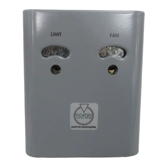
The White-Rodgers combination warm air limit and single
speed fan control combines into one compact case, a switch
which controls the fan or blower operation and also a switch
which acts as a safety limit control.
The fan switch is designed to control blower operation. It will
start the fan circulating warm air when the bonnet temperature
reaches the pre-determined temperature setting; stopping the
fan and when the bonnet temperature falls below the pre-
determined setting.
The warm air limit switch is designed to act as a safety switch
which automatically shuts off the burner when the furnace
temperature reaches a dangerously high point, regardless of
the cause.
The limit switch of these controls has special contacts which are
suitable for use on low voltage and millivolt (thermocouple
generator type) circuits as well as line voltage equipment such
as gas valves, oil burner motors, etc.
THESE CONTROLS MUST BE INSTALLED BY A QUALIFIED
INSTALLER.
Do not exceed the specification ratings.
All wiring must conform to local and national electrical codes and
ordinances.
This control is a precision instrument, and should be handled
carefully. Rough handling or distorting components could cause
the control to malfunction.
This control has been accurately calibrated at the factory. any
attempt to calibrate this control will void the White-Rodgers
warranty.
If the furnace manufacturer has made provision for, or recom-
mendations for location of this control, then follow those instruc-
tions. If not, the following suggestions should be observed.
The temperature sensitive bulbs should be positioned in the
furnace bonnet so that they will be located in the area which is
subjected to the most rapid temperature changes.
WHITE-RODGERS DIVISION
EMERSON ELECTRIC CO.
9797 REAVIS RD., ST. LOUIS, MO. 63123
(314) 577-1300, FAX (314) 577-1517
9999 HWY. 48, MARKHAM, ONT. L3P 3J3
(905) 475-4653, FAX (905) 475-4625
TYPE 5A75
FAN & LIMIT CONTROL
INSTALLATION INSTRUCTIONS
To prevent electrical shock and/or equipment damage,
disconnect electric power to system at main fuse or
circuit breaker box until installation is complete.
Do not use on circuits exceeding specified volt-
age. Higher voltage will damage control and could
cause shock or fire hazard.
Avoid locations where there may be dead air spots or stratifica-
tion affecting free air circulation. Corners, sharp turns, baffles or
other obstructions usually cause these conditions. Do not locate
the control elements where the air-flow from the bonnet into any
single duct will control its operation.
Printed in U.S.A.
DESCRIPTION
PRECAUTIONS
CAUTION
WARNING
INSTALLATION
PART NO. 37-0874C
Replaces 37-0874-1 & 37-9098
9549
Advertisement
Table of Contents

Subscribe to Our Youtube Channel
Related Manuals for White Rodgers 5A75


Summary of Contents for White Rodgers 5A75
-
Page 1: Installation Instructions
TYPE 5A75 WHITE-RODGERS FAN & LIMIT CONTROL INSTALLATION INSTRUCTIONS Operator: Save these instructions for future use! FAILURE TO READ AND FOLLOW ALL INSTRUCTIONS CAREFULLY BEFORE INSTALLING OR OPERATING THIS CONTROL COULD CAUSE PERSONAL INJURY AND/OR PROPERTY DAMAGE. DESCRIPTION The White-Rodgers combination warm air limit and single... - Page 2 (right hand switch) as shown in the TYPE diagram on this page. 5A75 Connect the limit side (left hand switch) according to wiring diagrams packed with the primary control, gas valve, oil burner control or stoker control.
- Page 3 SETTING THE CONTROL (CONT.) FAN SWITCH WITH ADJUSTABLE DIFFERENTIAL To set the control: Use a screwdriver in the adjusting slot (A) on the front of the The movable indicator points to the temperature at which the control to turn the dial so that the fixed indicator (B) points contacts close.
- Page 4 TYPE 5A75 LIMITEUR ET COMMANDE WHITE-RODGERS DE VENTILATEUR INSTRUCTIONS D’INSTALLATION Utilisateur : conservez ces instructions pour vous y référer au besoin ! SI VOUS NE LISEZ PAS ATTENTIVEMENT CES INSTRUCTIONS AVANT D’INSTALLER ET D’UTILISER LA COMMANDE, VOUS RISQUEZ DE CAUSER DES BLESSURES ET DES DOMMAGES MATÉRIELS.
- Page 5 (SI UTILISÉ) dans le schéma ci-contre. TYPE Raccorder le limiteur (côté gauche) selon les schémas de 5A75 câblage fournis avec la commande principale, le robinet à gaz, la commande de brûleur à mazout ou la commande de chargeur SOUS automatique.
- Page 6 RÉGLAGE DE LA COMMANDE (suite) COMMUTATEUR DE VENTILATEUR À DIFFÉRENTIEL Pour régler la commande : RÉGLABLE 1. Introduire la pointe d’un tournevis dans la fente de réglage L’indicateur mobile donne la température à laquelle les contacts (A) qui se trouve à l’avant de la commande. Tourner le seront fermés.
Need help?
Do you have a question about the 5A75 and is the answer not in the manual?
Questions and answers