Advertisement
Available languages
Available languages
Quick Links
WHITE-RODGERS
Operator: Save these instructions for future use!
FAILURE TO READ AND FOLLOW ALL INSTRUCTIONS CAREFULLY BEFORE
INSTALLING OR OPERATING THIS CONTROL COULD CAUSE PERSONAL
INJURY AND/OR PROPERTY DAMAGE.
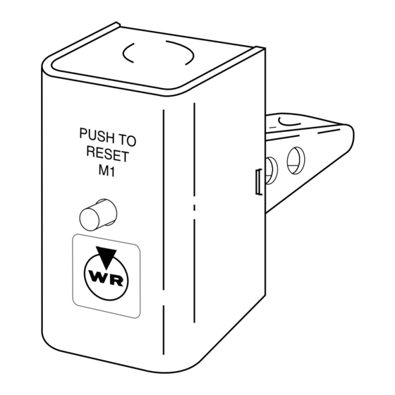
This high limit control is of the non-cycling manual reset
type; once the contacts open, they will remain open until
the reset button is pushed.
This control is designed to break a line voltage (or low
voltage) circuit if air temperature at its element location
ever reaches its predetermined cut-out setting.
This control may be used to protect against high tempera-
tures in heating and ventilation systems by opening circuit
to burner if circulated air reaches a temperature above the
fixed setting of the control. It is also suitable for use on
downflow furnaces to lock out burner in event of blower
failure or slow start.
CAUTION
!
To prevent electrical shock and/or equipment
damage, disconnect electric power to Furnace at
main fuse or circuit breaker box, until installation
is complete.
ELECTRICAL DATA
Electrical Rating:
Motor Loads –
10 FLA (60 LRA), 120V 60 Hz.
6 FLA (36 LRA), 240V 60 Hz.
Valves & Relays– 4A @ 25V 60 Hz.
SWITCH ACTION: Open On Rise, Manual Reset
Follow any wiring instructions provided by the furnace
manufacturer. Typical diagram is shown for normal use of
this control. A normal cycling type high limit control should
always be used in addition to the High Limit Control for
monitoring burner operation.
All wiring should be installed according to local and
national electrical codes and ordinances. Controls
are required to be installed with 75
LOCATION:
Normal use of this control requires that it be located
in the return air duct where the sensing element will
be subjected to normal flow of air returning to the
furnace.
This control has a fixed setting. If temperature ever reaches the cut-out setting, the contacts will open. When
temperature drops to safe level, the reset button must be pushed before contacts will reclose.
WHITE-RODGERS DIVISION
EMERSON ELECTRIC CO.
9797 REAVIS RD., ST. LOUIS, MO. 63123
(314) 577-1300, Fax (314) 577-1517
9999 HWY. 48, MARKHAM, ONT. L3P 3J3
(905) 475-4653, FAX (905) 475-4625
R
Do not use on circuits exceeding specified volt-
ages. Higher voltages will damage control and
could cause shock or fire hazard.
THERMAL DATA
Cut-Out Range: 125° – 250°F (52° – 121°C)
Standard Cut-Out Settings: 125°, 165°, 200°, 240°F
(52°, 74°, 93°, 116°C)
Element Insertion Length: 3 Inches
L1
L2
°
C minimum wire.
BLOWER
MOTOR
Printed in U.S.A.
5C06
High Limit Control
Open On Rise, Manual Reset
INSTALLATION INSTRUCTIONS
WARNING
!
FAN CONTROL
HOT
POWER SUPPLY
Fig.1-Diagram for shutting off burner
DESCRIPTION
PRECAUTIONS
SPECIFICATIONS
WIRING
5C06 HIGH LIMIT CONTROL
TO OIL BURNER
OR GAS VALVE
(LINE VOLTAGE)
ADJUSTMENT
PART NO. 37-2398D
Replaces 37-2398C
9507
Advertisement

Subscribe to Our Youtube Channel
Related Manuals for White Rodgers 5C06


Summary of Contents for White Rodgers 5C06
- Page 1 Follow any wiring instructions provided by the furnace manufacturer. Typical diagram is shown for normal use of FAN CONTROL 5C06 HIGH LIMIT CONTROL this control. A normal cycling type high limit control should always be used in addition to the High Limit Control for monitoring burner operation.
- Page 2 Veuillez suivre les directives de câblage fournies par le fabricant LIMITEUR À COMMANDE DU de l’appareil de chauffage. Le schéma de câblage typique ci- MAXIMUM 5C06 VENTILATEUR contre correspond à une utilisation normale de la commande. Toujours utiliser un limiteur à maximum ordinaire à cycles en plus de celui-ci afin de contrôler le fonctionnement du brûleur.
Need help?
Do you have a question about the 5C06 and is the answer not in the manual?
Questions and answers