Table of Contents
Advertisement
Available languages
Available languages
Quick Links
WHITE-RODGERS
Operator: Save these instructions for future use!
FAILURE TO READ AND FOLLOW ALL INSTRUCTIONS CAREFULLY BEFORE
INSTALLING OR OPERATING THIS CONTROL COULD CAUSE PERSONAL
INJURY AND/OR PROPERTY DAMAGE.
These water valves provide a low cost system of zoned tem-
perature control wherever hot water is the heating medium. In
new construction, the heating piping system can be laid out to
produce any number of independent temperature controlled
zones by use of these valves.
In existing buildings, a variety of zone heating combinations can
be obtained, depending on the particular piping lay-outs. Each
zone requires one water valve and one thermostat, but only
one circulator is required for the entire system. New con-
struction properly piped, will not require flow control valves,
since the water valve itself performs this function.
Existing construction, where flow control valves have been
installed, will operate quite satisfactorily without removing the
existing flow control valves.
This zone valve motor is intended for use with a low voltage
system; do not use this zone valve with a millivolt or line voltage
system. If in doubt about whether your wiring is millivolt, line or
low voltage, have it inspected by a qualified heating contractor
or electrician.
Do not exceed the specification ratings.
All wiring must conform to local and national electrical codes and
ordinances.
CAUTION
!
To prevent injuries from scalding always drain system
before unlatching valve assembly from body.
Maximum water temperature: 240°F (115°C)
Maximum system pressure: 50 PSI
Differential across valve: 15 PSI
Electrical Rating:
Valve Motor: 25 VAC (.40 Amp.)
Auxiliary Contacts: Do not exceed 2.0 Amp. at 25 VAC
(Terminals 2 and 3)
The schematic shows the valve in the closed position. As the
thermostat calls for heat, the valve motor is energized and
begins to open the valve. Soon thereafter side "A" of motor
switch makes with the holding contacts. This contact provides a
holding circuit to prevent the valve from stopping part way
through its cycle if the thermostat is changed to the satisfied
WHITE-RODGERS DIVISION
EMERSON ELECTRIC CO.
9797 REAVIS RD., ST. LOUIS, MO. 63123
(314) 577-1300, Fax (314) 577-1517
9999 HWY. 48, MARKHAM, ONT. L3P 3J3
(905) 475-4653, FAX (905) 475-4625
All guarantees are void if these specifications are exceeded.
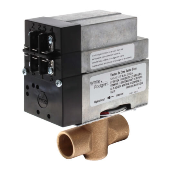
TYPE 1311
HYDRONIC ZONE VALVES
Installation INSTRUCTIONS
To prevent electrical shock and/or equipment damage,
disconnect electric power to system at main fuse or
circuit breaker box until installation is complete.
Do not use on circuits exceeding specified voltages.
Higher voltages will damage control and could cause
shock or fire hazard.
Timing: Approximately 45 seconds from full open to full close
or full close to full open.
Friction loss equivalents:
3/4" valve – 2-1/2 ft. copper tubing
1" valves – 4 ft. copper tubing
1-1/4" valves – 7 ft. copper tubing
PRINCIPLE OF OPERATION
position. Just before the valve reaches the full-open position,
side "B" of motor switch closes (providing a low voltage auxiliary
circuit for starting burner and/or circulator). The motor stops with
the valve in the open position when side "A" of motor switch
breaks the holding contact. (Completing a circuit through con-
tact "6" and the thermostat anticipator.)
Printed in U.S.A.
(3 WIRE)
DESCRIPTION
PRECAUTIONS
CAUTION
!
WARNING
!
SPECIFICATIONS
PART NO. 37-5421B
Replaces 37-5421A
9812
Advertisement
Table of Contents

Related Manuals for White Rodgers 1311


Summary of Contents for White Rodgers 1311
- Page 1 TYPE 1311 HYDRONIC ZONE VALVES WHITE-RODGERS (3 WIRE) INSTALLATION INSTRUCTIONS Operator: Save these instructions for future use! FAILURE TO READ AND FOLLOW ALL INSTRUCTIONS CAREFULLY BEFORE INSTALLING OR OPERATING THIS CONTROL COULD CAUSE PERSONAL INJURY AND/OR PROPERTY DAMAGE. DESCRIPTION These water valves provide a low cost system of zoned tem- perature control wherever hot water is the heating medium.
- Page 2 PRINCIPLE OF OPERATION (Continued) When thermostat is satisfied, the valve motor is again ener- NOTE: INTERNAL PARTS AND MOTOR SHAFT: WIRING OF WATER VALVE. gized. Just after the valve starts to close, side “A” of motor switch Revolves in 90° intervals JUMPER WIRES with each thermostat cycle.
- Page 3 If the boiler manufacturer recommends a wiring diagram, follow his instructions. If none are available, the following diagrams show suggested circuits for Type 1311 Water Valves in conjunc- tion with other W-R controls. A 40 VA transformer will handle up to four (4) water valves. A 20 VA transformer will handle up to two (2) water valves.
- Page 4 WIRING – Continued DIAGRAM FOR SYSTEMS WHERE INTERNAL TRANSFORMER OF RELAY-HOT WATER CONTROL SUPPLIES POWER FOR ZONE VALVES TO LOW VOLTAGE GAS VALVE TYPE 842A-16 LINE TYPE 8F43A ADDITIONAL CIRCULATOR TO ZONE ZONES TYPE 8F42A MOTOR TO ZONE VALVES VALVES LINE TO 24 VAC LINE...
- Page 5 TYPE 1311 ROBINETS DE ZONE HYDRONIQUES WHITE-RODGERS (À TROIS FILS) INSTRUCTIONS D’INSTALLATION Utilisateur : conservez ces instructions pour vous y référer au besoin ! SI VOUS NE LISEZ PAS ATTENTIVEMENT CES INSTRUCTIONS AVANT D’INSTALLER ET D’UTILISER LA COMMANDE, VOUS RISQUEZ DE CAUSER DES BLESSURES ET DES DOMMAGES MATÉRIELS.
- Page 6 PRINCIPE DE FONCTIONNEMENT (suite) ARBRE DU MOTEUR : maintien. Le côté B du commutateur du moteur ouvre le circuit NOTE : PIÈCES ET Il tourne de 90° à chaque CÂBLAGE INTERNES auxiliaire et le côté A du commutateur établit le contact avec la CAVALIERS cycle du thermostat.
- Page 7 (2) robinets. SCHÉMA POUR LES SYSTÈMES DONT LE BRÛLEUR ET LE CIRCULATEUR FONCTIONNENT INDÉPENDAMMENT DU THERMOSTAT. SOUS TENSION Fig. 6 Utilisation d’un robinet de zone type 1311 CIRCUIT ZONES SUPPLÉMENTAIRES TRANSFORMATEUR SCHÉMA POUR LES SYSTÈMES DONT LE TRANSFORMATEUR INTERNE DU RELAIS DE COMMANDE ALIMENTE LES ROBINETS DE ZONE LIMITEUR À...
- Page 8 CÂBLAGE (suite) SCHÉMA POUR LES SYSTÈMES DONT LE TRANSFORMATEUR INTERNE DE LA COMMANDE D’EAU CHAUDE À RELAIS ALIMENTE LES ROBINETS DE ZONE VERS LE ROBINET À GAZ À BASSE TENSION TYPE 842A-16 SOUS TENSION CIRCUIT ZONES MOTEUR DU SUPPLÉMENTAIRES TYPE 8F43A CIRCULATEUR TYPE 8F42A VERS LES...
Need help?
Do you have a question about the 1311 and is the answer not in the manual?
Questions and answers