Advertisement
FAILURE TO READ AND FOLLOW ALL INSTRUCTIONS CAREFULLY
BEFORE INSTALLING OR OPERATING THIS CONTROL COULD CAUSE
PERSONAL INJURY AND/OR PROPERTY DAMAGE.
The 36J27 combination gas valve is designed for
direct spark ignition (DSI) and hot surface ignition
(HSI) system applications. This control is equipped
with redundant and main solenoid valves that control
gas flow to the main burners, a pressure regulator
and a two-position on/off switch for regulation
and electrical shut-off of the solenoid valves. Upon
signal from an integrated furnace control, the valve
modulates outlet pressure.
Pressure Regulator Adjustment Range ( inches W.C.)
CSA Std. Gas
Pipe Sizes
(1000 BTU/CU. FT.)
20,000 - 210,000
1/2" x 1/2" NPT
Pipe Sizes (NPT)
1/2" x 1/2" (Vertical or Upright)
Ambient Temperature .... -40° to 175°F
Pressure Rating .............. 14" W.C. (1⁄2 PSI) max.
Voltage ........................... 24 VAC
Frequency....................... 60 Hz
Total Current .................. 1.0A
Pulse Width Modulation (PWM):
Modulation ..................... 35% - 100% opening
Regulator Vent Outlet .... accepts 5/16" I.D. hose
Rotary dip switch for pressure regulation adjustment
Precalibrated for LP - simplifies conversion
DSI and HSI Modulating Combination Gas Valve
INSTALLATION INSTRUCTIONS
LP Gas
.64 Sp. Gr.
1.53 Sp. Gr.
(2500 BTU/CU. FT.)
32,600 - 340,000
BTU/HR
BTU/HR
For L.P. Gas Use Conversion Kit F92-1021
1.0" Pressure Drop Capacity
CSA Std. Gas
(1000 BTU/CU. FT.)
140,000 BTU/HR
Low level: 0 - .03 volts
High level: 3 - 5.5 volts
with 1% increments
www.white-rodgers.com
www.emersonclimate.com
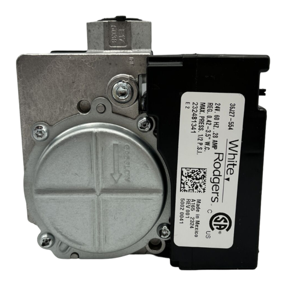
36J27-554
Fig. 1 - 36J27 Modulating Gas Valve
SPECIFICATIONS
Adjustment
Range
(NAT., IN. W.C.)
0.40 - 4.0
.64 Sp. Gr.
CONTENTS
Description ................................................ 1
Specifications ............................................. 1
Mounting Positions ......................................... 2
Precautions ................................................ 3
Installation ................................................. 4
Adjustment ................................................ 5
Pressure Regulator Adjustment
Lighting Instructions.................................... 6
DESCRIPTION
CONTROL LABEL
Adjustment
Range
(LP., IN. W.C.)
1.3 - 11.5
LP Gas
1.53 Sp. Gr.
(2500 BTU/CU. FT.)
226,800 BTU/HR
PART NO. 37-7004D
Replaces 37-7004C
1345
Advertisement

Related Manuals for White Rodgers 36J27-554


Summary of Contents for White Rodgers 36J27-554
-
Page 1: Table Of Contents
36J27-554 DSI and HSI Modulating Combination Gas Valve INSTALLATION INSTRUCTIONS FAILURE TO READ AND FOLLOW ALL INSTRUCTIONS CAREFULLY BEFORE INSTALLING OR OPERATING THIS CONTROL COULD CAUSE PERSONAL INJURY AND/OR PROPERTY DAMAGE. DESCRIPTION The 36J27 combination gas valve is designed for direct spark ignition (DSI) and hot surface ignition (HSI) system applications. -
Page 2: Mounting Positions
MOUNTING POSITIONS UPRIGHT, OR 0° TO 90° FROM UPRIGHT Upright (inlet left) Vertical (inlet bottom) Vertical (inlet top) 90° from Upright (inlet left) Vertical (inlet bottom) Vertical (inlet top) 90° from Upright (inlet bottom) Fig. 2 – Valve Mounting 3.000 MAX. SWING RADIUS Upright Length ........ -
Page 3: Precautions
PRECAUTIONS DO NOT BEGIN INSTALLATION UNTIL YOU READ THE FOLLOWING PRECAUTIONS. If you do not follow these instructions exactly, a fire or explosion WARNING may result, causing property damage, personal injury or loss of life. 1. Failure to turn off electric or main gas supply 5. -
Page 4: Installation
INSTALLATION 1. Turn off electrical power to the system at the 6. If you are using a vise or open-end wrench to fuse box or circuit breaker. Also turn off the hold the valve while installing piping, do not main gas supply. tighten excessively, as this may damage the valve. -
Page 5: Adjustment
INSTALLATION ELECTRICAL 5 PIN CONNECTOR PIN 1 LOCATION INLET PRESSURE TAP POST OUTLET REGULATOR PRESSURE VENT VALVE INLET TAP POST VALVE OUTLET Electrical 5 PIN Connector Pin Out PIN 5 - TH - Main Valve 24 VAC (top pin, with the cover pointing up) PIN 4 - TR - Ground PIN 3 - TX - Communication to IFC PIN 2 - RX - Communication to Stepper... -
Page 6: Lighting Instructions
LIGHTING INSTRUCTIONS FOR YOUR SAFETY READ BEFORE OPERATING If you do not follow these instructions exactly, a fire or explosion WARNING may result, causing property damage, personal injury or loss of life. A. This appliance does not have a pilot. It is equipped •... - Page 7 NOTES...
- Page 8 White-Rodgers is a business of Emerson Electric Co. The Emerson logo is a www.white-rodgers.com trademark and service mark of Emerson Electric Co. www.emersonclimate.com...
Need help?
Do you have a question about the 36J27-554 and is the answer not in the manual?
Questions and answers