Table of Contents
Advertisement
Quick Links
Operator: Save these instructions for future use!
FAILURE TO READ AND FOLLOW ALL INSTRUCTIONS CAREFULLY BEFORE
INSTALLING OR OPERATING THIS CONTROL COULD CAUSE PERSONAL
INJURY AND/OR PROPERTY DAMAGE.
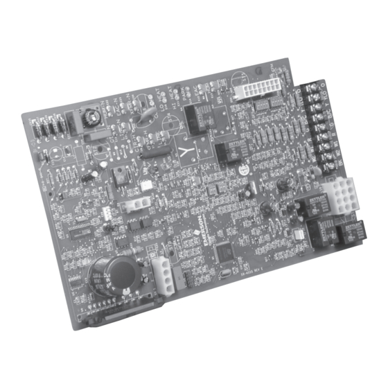
The 50V64-743 is a two-stage automatic gas interrupted ignition
control employing a microprocessor to continually monitor,
analyze, and control the proper operation of the gas burner and
inducer, and provide signal for proper operation of variable fan
speed timing.
Signals interpreted during continual surveillance of the two-
stage thermostat and flame sensing element initiate automatic
ignition of the burner, sensing of the flame, and system shutoff
during normal operation.
The control incorporates system fault analysis for quick gas
flow shutoff, coupled with automatic ignition retry upon sensing
a fault correction.
GENERAL PRECAUTION
!
Application of this type of control may cause flame
rollout on initial startup and could cause personal
injury and/or property damage.
Replace only with exact model number, including dash
number. Failure to use exact replacement control could
cause personal injury and/or property damage.
If in doubt about whether your wiring is millivolt, line, or low volt-
age, have it inspected by a qualified heating and air conditioning
contractor or licensed electrician.
Do not exceed the specification ratings.
All wiring must conform to local and national electrical codes
and ordinances.
This control is a precision instrument, and should be handled
carefully. Rough handling or distorting components could cause
the control to malfunction.
CONTENTS
Description ............................................................. 1
Precautions ............................................................ 1
Specifications ......................................................... 2
Operation ................................................................ 2
Installation .............................................................. 5
Mounting & Wiring
Integrated Furnace Control
for Furnaces with Variable Fan Speed
INSTALLATION INSTRUCTIONS
To prevent electrical shock and/or equipment damage,
disconnect electric power to system at main fuse or
circuit breaker box until installation is complete.
This control is not intended for use in locations where
it may come in direct contact with water. Suitable
protection must be provided to shield the control from
exposure to water (dripping, spraying, rain, etc.).
Label all wires prior to disconnection when servicing
controls. Wiring errors can cause improper and
dangerous operation.
Following installation or replacement, follow appliance
manufacturers' recommended installation/service
instructions to insure proper operation.
Do not use on circuits exceeding specified voltage.
Higher voltage will damage control and could cause
shock or fire hazard.
Do not short out terminals on gas valve or primary
control to test. Short or incorrect wiring will damage
thermostat and could cause personal injury and/or
property damage.
www.white-rodgers.com
www.emersonclimate.com
50V64-743
DESCRIPTION
PRECAUTIONS
CAUTION
!
WARNING
!
PART NO. 37-7565A
1503
Advertisement
Table of Contents

Subscribe to Our Youtube Channel
Related Manuals for White Rodgers 50V64-743


Summary of Contents for White Rodgers 50V64-743
- Page 1 INSTALLING OR OPERATING THIS CONTROL COULD CAUSE PERSONAL INJURY AND/OR PROPERTY DAMAGE. DESCRIPTION The 50V64-743 is a two-stage automatic gas interrupted ignition control employing a microprocessor to continually monitor, analyze, and control the proper operation of the gas burner and inducer, and provide signal for proper operation of variable fan speed timing.
-
Page 2: Specifications
If W1 and W2 are tied together, the time delay of second stage is based on the switch settings of SW1, per the following table. Switches on the 50V64-743 control are used to control functions of the circulator blower. Switches labeled SW3 and SW4 control SW1 SWITCH POSITIONS the circulator blower speed. -
Page 3: Heat Mode
After the optional delay-to-fan-off period The Silicon Nitride ignitor manufactured by White-Rodgers ends, the circulator “E” output and air cleaner are de-energized. must be used. These ignitors are specially designed to operate... -
Page 4: Diagnostic Features
OPERATION with the gas valve de-energized, interrupting the call for 5 flashes, then pause Flame sense when no flame heat at the thermostat will not reset the control). should be present Interrupt the 24 VAC power at the control for at least five 6 flashes, then pause Line reverse polarity or ignitor seconds. - Page 5 TYPICAL SYSTEM WIRING TABLE 50V64 TERMINAL TYPE SYSTEM COMPONENT CONNECTION First stage call for heat Second stage call for heat Input for fan operation 24 VAC transformer (HIGH side) 9-screw 24 VAC transformer (LOW side) terminal block First stage call for cool Second stage call for cool Humidistat enable H/P or cooling mode...
- Page 6 TYPICAL SYSTEM WIRING DIAGRAM NEUTRAL 120 VAC (LINE) (LINE) 24 VAC CLASS II TRANSFORMER 24 VAC INTEGRATED FURNACE CONTROL XFMR-N LINE-N CIR-N HUM-N ELECTRONIC EAC-N HUMIDIFIER AIR CLEANER XFMR-H LINE FLAME SENSOR PROBE CIR-H IGN-H IGN-N IGNITOR IND-01 IND-02 INDUCER IND-03 IND-GND THERMOSTAT...
- Page 7 NOTES...
- Page 8 White-Rodgers is a business of Emerson Electric Co. The Emerson logo is a www.white-rodgers.com trademark and service mark www.emersonclimate.com of Emerson Electric Co.
- Page 9 Mouser Electronics Authorized Distributor Click to View Pricing, Inventory, Delivery & Lifecycle Information: White-Rodgers 50V64-743...
Need help?
Do you have a question about the 50V64-743 and is the answer not in the manual?
Questions and answers