Table of Contents
Advertisement
Quick Links
Operator: Save these instructions for future use!
FAILURE TO READ AND FOLLOW ALL INSTRUCTIONS CAREFULLY BEFORE
INSTALLING OR OPERATING THIS CONTROL COULD CAUSE PERSONAL
INJURY AND/OR PROPERTY DAMAGE.
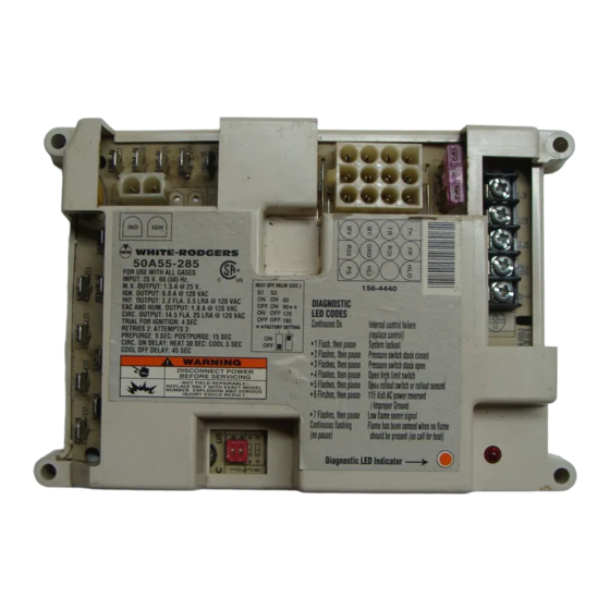
The 50A55-285 is an automatic gas interrupted ignition control
that employs a microprocessor to continually monitor, analyze,
and control the proper operation of the gas burner, inducer, and
fan.
Signals interpreted during continual surveillance of the thermo-
stat and flame sensing element initiate automatic ignition of the
burner, sensing of the flame, and system shut-off during normal
operation.
Installation should be done by a qualified heating and air
conditioning contractor or licensed electrician.
If in doubt about whether your wiring is millivolt, line, or low
voltage, have it inspected by a qualified heating and air condi-
tioning contractor or licensed electrician.
Do not exceed the specification ratings.
All wiring must conform to local and national electrical codes and
ordinances.
This control is a precision instrument, and should be handled
carefully. Rough handling or distorting components could cause
the control to malfunction.
Following installation or replacement, follow manufacturer's
recommended installation/service instructions to ensure proper
operation.
CAUTION
Do not short out terminals on gas valve or primary
control. Short or incorrect wiring may damage the
thermostat.
CONTENTS
Description ......................................................... 1
Precautions ........................................................ 1
Specifications ..................................................... 2
Installation .......................................................... 3
Operation ........................................................... 6
Mounting Hole Template ..................................... 8
WHITE-RODGERS
EMERSON ELECTRIC CO.
9797 REAVIS ROAD
ST. LOUIS, MISSOURI 63123-5398
www.white-rodgers.com
Integrated Furnace Control
INSTALLATION INSTRUCTIONS
These controls incorporate system fault analysis for quick gas
flow shut-off, coupled with automatic ignition retry upon sensing
a fault correction.
WARNING
Failure to comply with the following
warnings could result in personal injury
or property damage.
FIRE HAZARD
• Do not exceed the specified voltage.
• Replace existing control with exact model and
dash number.
• Protect the control from direct contact with water
(dripping, spraying, rain, etc.).
• If the control has been in direct contact with water,
replace the control.
• Label all wires before disconnection when servic-
ing controls. Wiring errors can cause improper
and dangerous operation.
• Route and secure wiring away from flame.
SHOCK HAZARD
• Disconnect electric power before servicing .
• Ensure proper earth grounding of appliance.
• Ensure proper connection of line neutral and line
hot wires.
EXPLOSION HAZARD
• Shut off main gas to appliance until installation is
complete.
Printed in U.S.A.
50A55-285
DESCRIPTION
PRECAUTIONS
PART NO. 37-6100C
Replaces 37-6100B
0150
Advertisement
Table of Contents

Subscribe to Our Youtube Channel
Summary of Contents for White Rodgers 50A55-285
-
Page 1: Table Of Contents
INSTALLING OR OPERATING THIS CONTROL COULD CAUSE PERSONAL INJURY AND/OR PROPERTY DAMAGE. The 50A55-285 is an automatic gas interrupted ignition control that employs a microprocessor to continually monitor, analyze, and control the proper operation of the gas burner, inducer, and fan. -
Page 2: Specifications
COOL DELAY-TO-FAN-OFF AUTO RESET HUMIDIFIER ELECTRONIC AIR CLEANER * These times will vary depending on option switch position. The control is factory-set at 90 sec. HEAT delay-to-fan-off. See OPERATION section for further information. 50A55-285 2 times 60/90/ 120/180 60 minutes... -
Page 3: Installation
WARNING FIRE HAZARD • Do not exceed the specified voltage. • Replace existing control with exact model and dash number. • Protect the control from direct contact with water (dripping, spraying, rain, etc.). • Label all wires before disconnection when servic- ing controls. - Page 4 (LINE) HUMIDIFIER ELECTRONIC AIR CLEANER FLAME SENSOR PROBE LEGEND Low Voltage (24 VAC) Line Voltage (120 VAC) N. C. = Normally closed switch N. O. = Normally open switch TYPICAL SYSTEM WIRING DIAGRAM 120 VAC 24 VAC CLASS II TRANSFORMER 24 VAC 50A55 COOL...
- Page 5 TYPICAL SYSTEM WIRING TABLE 50A55 TERMINAL TERMINAL TYPE Terminal block with captive screws MV (2 terminals) 12-pin connector & harness (unused terminal) 2-pin connector & harness spade terminal COOL spade terminal HEAT spade terminal PARK (2 terminals) spade terminal LINE spade terminal XFMR spade terminal...
-
Page 6: Heat Mode
OPERATION OPTION SWITCHES The option switches on the 50A55-285 control are used to determine the length of the heat delay-to-fan-off periods. The following table shows the time periods that will result from the various switch positions. OPTION SWITCH POSITIONS HEAT delay-... - Page 7 SYSTEM LOCKOUT AND DIAGNOSTIC FEATURES SYSTEM LOCKOUT FEATURES When system lockout occurs, the gas valve is de-energized, the circulator blower is energized at heat speed, and, if flame is sensed, the inducer blower is energized. The diagnostic indica- tor light will flash or glow continuously to indicate system status. (System lockout will never override the precautionary fea- tures.) To reset the control after system lockout, do one of the...
-
Page 8: Mounting Hole Template
MOUNTING HOLE TEMPLATE MOUNTING HOLE TEMPLATE FOR MOUNTING HOLE LOCATIONS 4.172 .007 (2 plcs.) 6.402 .010 (2 plcs.) Refer to page 3 of the installation instructions for proper installation.


Need help?
Do you have a question about the 50A55-285 and is the answer not in the manual?
Questions and answers