Table of Contents
Advertisement
Available languages
Available languages
FAILURE TO READ AND FOLLOW ALL INSTRUCTIONS CAREFULLY BEFORE
INSTALLING OR OPERATING THIS CONTROL COULD CAUSE PERSONAL
INJURY AND/OR PROPERTY DAMAGE.
DESCRIPTION
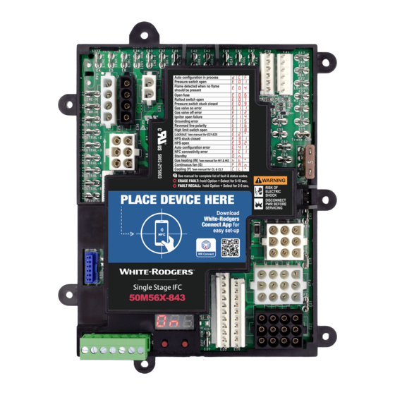
50M56X-843 is an aftermarket universal replacement control
kit for single stage furnace applications with PSC or ECMx
(constant torque) blower motors. A HotRod
is included to replace ignitors in most furnaces as well as
upgrade 80V systems to 120V.
With 50M56X-843 no complex adapter harnesses are
required, instead all connectors and terminals used in the
major OEM brands are included on the control itself. This
allows for OEM wiring to be connected directly to the control
for a faster and easier installation.
ELECTRICAL SPECIFICATIONS
Specification
Input Voltage
Input Current
Line Frequency
Inducer Relay at 120V
Gas Valve Relay @ 30V
Ignitor Relay @ 120V
PSC Circulator Relay
OPERATING TEMPERATURE RANGE:
-40° to 176°F (-40° to 80°C)
HUMIDITY RANGE:
5 to 95% relative humidity (non-condensing)
GASES APPROVED:
Natural, Manufactured, Mixed, Liquid Petroleum,
and LP Gas Air Mixtures
CONTENTS
Description ...................................................................... 1
Precautions ..................................................................... 1
Configuration .................................................................. 2
Installation ...................................................................... 3
Application & Operation Notes........................................ 5
Wiring Diagram ............................................................... 7
Troubleshooting.......................................................... ....11
INSTALLER MUST READ
APPLICATION AND OPERATION NOTES ON
PAGES 5, 6, & 7
TM
120V ignitor
Value
Unit
18-30
VAC
Max 800
mA
60
Hz
2.8A
FLA
1.5
Amperes
1.2
Amperes
10
FLA
emerson.com/white-rodgers
50M56X-843
Universal Integrated Single Stage
120V Hot Surface Ignition Control Kit
INSTALLATION INSTRUCTIONS
Included in the box:
• 1 - 50M56X-843 Ignition Control
• 1 - HotRod
Ignitor
TM
• 1 - Installation Instructions
• 4 - 1/2" Sheet Metal Mounting Screws
• 6 - 3/16" QC crimp on terminals
• 6 - 1/4" Female Spade Terminals
• 4 - Mounting Standoffs
WARNING
!
Failure to comply with the following warnings could result
in personal injury or pro perty damage.
• Installation should be done by a qualified heating and
air conditioning contractor or licensed electrician.
• All wiring must conform to local and national electrical
codes and ordinances.
• Following installation or replacement, follow
manufacturer's recommended installation/service
instructions to ensure proper operation.
FIRE HAZARD
• Do not exceed the specified voltage.
• Protect module from direct contact with water (dripping,
spraying, rain, etc.).
• If the module has been in direct contact with water,
replace the module.
• Label all wires before disconnection when servicing
modules. Wiring errors can cause improper and
dangerous operation.
• Route and secure wiring away from flame.
SHOCK HAZARD
• Disconnect electric power before servicing.
• Ensure proper earth grounding of appliance.
• Ensure proper connection of line neutral and line hot
wires.
• Ensure module has ¼" clearance between all sides of
module and grounded metal.
EXPLOSION HAZARD
• Shut off main gas to appliance until installation is
complete.
View Installation
Resources
PART NO. 37-7827001
2233
Advertisement
Chapters
Table of Contents

Subscribe to Our Youtube Channel
Related Manuals for White Rodgers 50M56X-843


Summary of Contents for White Rodgers 50M56X-843
-
Page 1: Table Of Contents
INSTALLING OR OPERATING THIS CONTROL COULD CAUSE PERSONAL INJURY AND/OR PROPERTY DAMAGE. DESCRIPTION 50M56X-843 is an aftermarket universal replacement control Included in the box: kit for single stage furnace applications with PSC or ECMx • 1 – 50M56X-843 Ignition Control (constant torque) blower motors. -
Page 2: Description
MOBILE APP CONFIGURATION (PREFERRED) For fastest setup, use White-Rodgers Connect App: 1. Download from iOS App Store or Google Play Store 2. Open White-Rodgers Connect App 3. Touch “Connect to Control” on the home page 4. Place Device above NFC Logo on Module, wait for check mark 5. -
Page 3: Installation
Initiates Self-Test Mode Note: Table 1 shows every configuration option available on 50M56X-843. However, not all OEMs use the same configuration options. Once the automatic configuration process is complete, some settings not relevant to the detected OEM application may no longer appear in the control’s menu or WR Connect app. - Page 4 3/16” spades but can be used to store old control wiring for reference. unused PSC (1/4”) or ECMx (3/16”) speed taps 3. Mount 50M56X-843 in the unit using one of the since PARK terminals do not provide an electrical mounting options noted in the Mounting section. Be connection to the attached motor leads.
-
Page 5: Application & Operation Notes
(always high) inducer motor and dedicated low cool speed a single stage blower motor. 50M56X-843 is able to operate • Dehumidify demand with a Y / Y2 input runs the blower these unique applications in addition to standard single at the cool speed for 10 minutes, then reduces the stage furnaces. - Page 6 Blower Type Selection and Speed Settings 50M56X-843 is able to replace furnaces with PSC or ECMx (constant torque) blower motors. The motor type present in the furnace must be configured by the installer based on the If encountered during replacement, simply snip off the wire options in the Configurations Menu option number 6 (BLr).
-
Page 7: Wiring Diagram
• White connectors on 50M56X-843 contain pins (which mate with harnesses containing sockets) Connectors with 50M56X-843 Connectors • White & black connectors on 50M56X-843 may mate • Identify connector type in OEM harness or on the with different colored harness connectors OEM control and plug OEM wiring directly onto matching •... - Page 8 WIRING DIAGRAM 6-Socket: Nordyne/Nortek Configuration 6-Socket: Rheem/Ruud Configuration DESCRIPTION DESCRIPTION IGNITOR HOT INDUCER HOT IGNITOR GNITOR NITO (OPEN) (OPEN) IGNITOR HOT IGNITOR NEUTRAL INDUCER NDUCER IGNITOR NITO INDUCER NEUTRAL INDUCER HOT (OPEN) (OPEN) 6-SOCKET 6-SOCKET INDUCER NEUTRAL IGNITOR NEUTRAL INDUCER 4-Pin: Goodman/Amana/Trane/American Standard/Lennox/ 4-Pin: Trane/American Standard Alt.
- Page 9 WIRING DIAGRAM 9-Socket: Goodman/Amana Configuration 9-Socket: Goodman/Amana Alt. Configuration DESCRIPTION DESCRIPTION (OPEN) (JUMPER TO PIN 4) PRESSURE SWITCH OUT PRESSURE SWITCH OUT XFMR TRANSFORMER HIGH TRANSFORMER HIGH XFMR (OPEN) (JUMPER TO PIN 1) HIGH LIMIT IN HIGH LIMIT IN TRANSFORMER RETURN TRANSFORMER RETURN MAIN VALVE OUT MAIN VALVE OUT...
- Page 10 WIRING DIAGRAM 10-Pin Inline: Trane/American Standard 10-Pin Inline: Trane/American Standard Alt. Configuration FLAME SENSOR F LA ME S DESCRIPTION FLAME SENSOR AME SEN ME SEN DESCRIPTION INDUCER LIMIT IN OPEN TRANSFORMER RETURN TRANSFORMER RETURN PRESSURE SWITCH IN PRESSURE SWITCH IN HIGH LIMIT OUT HIGH LIMIT OUT MAIN VALVE COMMON...
-
Page 11: Troubleshooting
TROUBLESHOOTING Table 2: 7-Segment Display Codes Condition LED 1 LED 2 LED 3 Comment/Troubleshoot Step Line Frequency Error / Internal Fault Verify 60 Hz line frequency, Replace control Pressure Switch Open Check pressure switch, inducer, and flue Flame Detected When no Flame Check gas valve for proper operation, check gas Should be Present valve and safety limit wiring... - Page 12 • Upon self-test mode entry, the display will flash 3 sets of dashes (- - -) 3 times 50M56X-843 has an advanced flame current sense circuit • If any error codes have been stored, they will be that allows the control to digitally measure and report flame...
- Page 13 DIRECTIVES AVANT L’INSTALLATION OU L’UTILISATION DE CETTE COMMANDE PEUT CAUSER DES BLESSURES OU DES DOMMAGES MATÉRIELS. DESCRIPTION La commande 50M56X-843-843 est une trousse de commande Inclus dans la boîte de rechange universelle du marché des pièces de rechange pour • 1 – Commande d’allumage 50M56X-843 les fournaises mono-étage avec moteurs du souffleur à...
-
Page 14: Description
CONFIGURATION AVEC L’APPLICATION MOBILE (PRÉFÉRABLE) Pour une configuration rapide, utilisez l’application White-Rodgers Connect : 1. Téléchargez l’application sur iOS App Store ou Google Play Store Lisez-moi 2. Ouvrez l’application White-Rodgers Connect 3. Appuyez sur « Connect to Control » (se connecter à la commande) sur la page d’accueil 4. -
Page 15: Installation
(non, oui) Initie le mode auto-test Remarque : Le Tableau 1 montre toutes les options de configuration disponibles sur la commande 50M56X-843. Toutefois, les fabricants d’origine n’utilisent pas tous les mêmes options de configuration. Une fois le processus de configuration automatique terminé, certains réglages non pertinents pour l’application d’origine détectée peuvent ne plus s’afficher dans le menu de la... - Page 16 5. Branchez tous les fils individuels restants sur le panneau aux codes et ordonnances locaux et nationaux de l’électricité. de commande 50M56X-843 en vous reportant à la section Schémas de câblage, au besoin. 1. Débranchez l’alimentation électrique et l’alimentation de gaz 6.
-
Page 17: Notes Sur Les Applications Et Le Fonctionnement
à brochages variés dans • Les systèmes mis à niveau avec la commande le même connecteur de la commande 50M56X-843, ce qui 50M56X-843 peuvent être jumelés avec un climatiseur élimine la nécessité d’inclure des faisceaux adaptateurs dans la ou une thermopompe à... - Page 18 à l’installation de la commande et à sa vérification. Sélection du type de ventilateur soufflant et réglages de vitesse La commande 50M56X-843 peut remplacer les fournaises avec moteurs de ventilateurs soufflants PSC ou ECMx (couple constant). Le type de moteur présent dans la fournaise doit être configuré...
- Page 19 1/4 po ou FLAMME DÉTECTÉE 3/16 po Jumelage approprié des connecteurs de faisceaux • Les connecteurs blancs de la commande 50M56X-843 contiennent des tiges (qui se marient aux faisceaux de câblage d’origine avec les connecteurs de la contenant des prises) commande 50M56X-843 •...
- Page 20 SCHÉMA DE CÂBLAGE 6 prises : Configuration Nordyne / Nortek 6 prises : Configuration Rheem/Ruud DESCRIPTION DESCRIPTION INDUCTEUR CHARGÉ ALLUMEUR CHARGÉ (OUVERT) (OUVERT) ALLUMEUR LLUMEU ALLUMEUR NEUTRE ALLUMEUR CHARGÉ INDUCTEUR NDUCTEU ALLUMEUR LUME INDUCTEUR NEUTRE INDUCTEUR CHARGÉ (OUVERT) (OUVERT) 6 PRISES 6 PRISES INDUCTEUR NEUTRE ALLUMEUR NEUTRE...
- Page 21 SCHÉMA DE CÂBLAGE 9 prises : Configuration Goodman / Amana 9 prises : Config. alt. Goodman / Amana DESCRIPTION DESCRIPTION (OUVERT) (CAVALIER À TIGE 4) SORTIE MANOSTAT SORTIE MANOSTAT XFMR TRANSFORMATEUR HAUTE TENSION TRANSFORMATEUR HAUTE TENSION XFMR (OUVERT) (CAVALIER À TIGE 1) ENTRÉE LIMITE ÉLEVÉE ENTRÉE LIMITE ÉLEVÉE RETOUR DU TRANSFORMATEUR...
- Page 22 SCHÉMA DE CÂBLAGE 10 tiges en ligne : Trane/American Standard 10 tiges en ligne : Configuration alt. Trane/ American Standard CAPTEUR DE FLAMME DESCRIPTION CAPTEUR DE FLAMME PTEUR D TEUR D DESCRIPTION ENTRÉE DE LIMITE D’’INDUCTEUR OUVERT RETOUR DU TRANSFORMATEUR RETOUR DU TRANSFORMATEUR ENTRÉE PRESSOSTAT ENTRÉE PRESSOSTAT...
-
Page 23: Dépannage
DÉPANNAGE Tableau 2 : Codes d’affichage à 7 segments Condition DEL 1 DEL 2 DEL 3 Commentaire/Étape de dépannage Assurez-vous que la ligne a une fréquence de 60 Hz, puis Erreur de fréquence de ligne / panne interne remplacez la commande Vérifiez le fonctionnement du manostat, de l’inducteur et de la Pressostat en position ouverte tubulure. - Page 24 • Lorsque l’on accède au mode d’auto-essai, l’afficheur fait clignoter 3 tirets (- - -) à 3 reprises La commande 50M56X-843 est équipée d’un circuit de • Si des codes d’erreur ont été sauvegardés, ils s’affichent, détection de courant de la flamme avancé qui lui permet de et si aucun code d’erreur n’a été...
Need help?
Do you have a question about the 50M56X-843 and is the answer not in the manual?
Questions and answers