Table of Contents
Advertisement
Available languages
Available languages
FAILURE TO READ AND FOLLOW ALL INSTRUCTIONS CAREFULLY
BEFORE INSTALLING OR OPERATING THIS CONTROL COULD CAUSE
PERSONAL INJURY AND/OR PROPERTY DAMAGE.
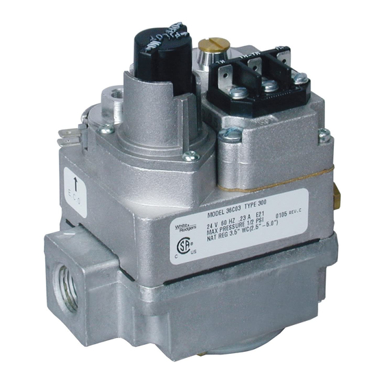
The 36C03 and 36C10 series valves are designed
to meet requirements for use on standing con-
tinuous pilot systems. 36C03 combination models
include a pressure regulator, 100% shut-off auto-
matic pilot, and main operator. 36C10 models do
not have a pressure regulator.
36C Inst
Voltage
36C03/36C10
36C03U
750mV
36C03A
f i r e - p a r t s . c o m
Pipe Size
(1000 BTU/cu. ft., 64
(inches)
1/2" x 3/8"
1/2" x 1/2"
1/2" x 3/4"
3/4" x 3/4"
PRESSURE REGULATOR ADJUSTMENT RANGE
EXCLUDING 36C10 NON-REGULATED
Gas Type
Natural Gas
LP Gas
Pilot Gas Outlet:
Located at outlet end of the valve
Type of Gas: Suitable for all domestic heating
gases
Ambient Temperature: -40º to 175ºF
Pressure Rating: 14" W.C. (1/2 PSI) Max
Voltage/Current: 36C03U - 750mV
36C03/36C10 - 24V/0.23A
36C03A - 120V/0.035A
36C03, 36C03A, 36C03U & 36C10
Standing/Continuous Pilot Combination Gas Valve
# of
Stages
Characteristics
24V
1
1
120V
1
PIPE SIZES/CAPACITIES
Capacity (BTU/hr) at
1" pressure drop across valve
Nat. Gas
Sp. Gr.)
100,000
230,000
230,000
280,000
Single Stage
2.5-5.0
7.5-12.0
www.white-rodgers.com
www.emersonclimate.com
INSTALLATION INSTRUCTIONS
ECO
Terminals
Open
Standing
Pilot
Fast
Yes
Fast
Yes
Fast
Yes
LP Gas
(2500 BTU/cu. ft.,
1.53 Sp. Gr.)
162,000
372,600
372,600
453,600
Parts and Accessories:
Conversion Kit
• F92-0659 Nat. to LP Gas (7.5" to 12.0" W.C.)
• F92-0737 Nat. to LP Gas (Non-regulated)
• F69-0727 1/4" brass compression fitting for pilot
line connection
Thermocouple (24V & 120V types):
Use W-R Type H06
Pilot Generator (.750 volt types):
Use W-R Type G01A-32
Description ........................................................................... 1
Specifications ....................................................................... 1
Precautions ........................................................................... 2
Installation ............................................................................ 3
Adjustment .......................................................................... 5
Lighting Instructions ............................................................ 6
Contents French ........................................................................ 9
Contents Spanish..................................................................... 17
DESCRIPTION
Intermittent Pilot
Proven Pilot
No
No
No
SPECIFICATIONS
Range of Regulation
Excluding 36C10 Non-Regulated
AGA Std. Nat. Gas
0.64 Sp. Gr.
(1,000 BTU/cu. ft.)
15,000 - 100,000
30,000 - 290,000
30,000 - 290,000
50,000 - 400,000
CONTENTS
PART NO. 37-7349B
HSI
DSI
No
No
No
No
No
No
LP Gas
1.53 Sp. Gr.
(2,500 BTU/cu. ft.)
15,000 - 162,000
30,000 - 469,000
30,000 - 469,000
50,000 - 648,000
Replaces 37-7349A
1429
Advertisement
Chapters
Table of Contents

Subscribe to Our Youtube Channel
Related Manuals for White Rodgers 36C03


Summary of Contents for White Rodgers 36C03
-
Page 1: Table Of Contents
FAILURE TO READ AND FOLLOW ALL INSTRUCTIONS CAREFULLY BEFORE INSTALLING OR OPERATING THIS CONTROL COULD CAUSE PERSONAL INJURY AND/OR PROPERTY DAMAGE. DESCRIPTION The 36C03 and 36C10 series valves are designed Terminals to meet requirements for use on standing con- tinuous pilot systems. 36C03 combination models include a pressure regulator, 100% shut-off auto- matic pilot, and main operator. -
Page 2: Precautions
SPECIFICATIONS MOUNTING POSITIONS Upright, 90 from upright or vertical INLET BOSS UPRIGHT UP OR DOWN LEFT OR RIGHT NOTE: Control shown may not be identical to replacement control Figure 1. Gas Valve Mounting Positions Figure 2. Valve Dimensions PRECAUTIONS DO NOT BEGIN INSTALLATION UNTIL YOU READ THE FOLLOWING PRECAUTIONS. -
Page 3: Installation
INSTALLATION 5. Apply pipe joint compound (pipe dope) or teflon MAIN PIPING CONNECTIONS tape that is approved for all gases, only to the NOTE male threads of the pipe joints. DO NOT apply compound or teflon tape to the first two threads All piping must comply with local codes, ordi- (see fig. -
Page 4: System Wiring
Transformer Thermostat f i r e - p a r t s . c o m Figure 5. Wiring for 36C03 (24 VAC) Figure 5. Wiring for 36C03(24 VAC) For appliances with an Electrical Cut Out (E.C.O.) For appliances without an device or supplementary high limit switch, Electrical Cut Out (E.C.O.) -
Page 5: Adjustment
INSTALLATION THERMOCOUPLE CONNECTION ENERGY CUT OFF (E.C.O.) (24 VAC AND 120 VAC MODELS) CONNECTION The thermocouple connection should be clean to A five-function valve uses the two E.C.O. termi- ensure good electrical contact. nals that are connected to the magnetic assembly where the thermocouple connects to the 36C Run the thermocouple nut into the power unit tapping as far as possible by hand. -
Page 6: Lighting Instructions
LIGHTING INSTRUCTIONS FOR YOUR SAFETY READ BEFORE OPERATING If you do not follow these instructions exactly, a fire or explosion WARNING may result, causing property damage, personal injury or loss of life. A. This appliance has a pilot that must be lighted by •... - Page 7 NOTES f i r e - p a r t s . c o m...
- Page 8 f i r e - p a r t s . c o m White-Rodgers is a business of Emerson Electric Co. The Emerson logo is a trademark and service mark www.white-rodgers.com of Emerson Electric Co. www.emersonclimate.com...
-
Page 9: Contents French
LIRE ET RESPECTER SOIGNEUSEMENT TOUTES LES INSTRUCTIONS AVANT L’INSTALLATION OU L’UTILISATION DE CET APPAREIL POUR PRÉVENIR LES BLESSURES ET LES DOMMAGES MATÉRIELS. DESCRIPTION Les robinets de la série 36C03 et 36C10 sont conçus Bornes pour respecter les normes d’utilisation applicables aux systèmes à pilote continu permanent. -
Page 10: Précautions
SPÉCIFICATIONS POSITIONS DE MONTAGE Droit, 90 degrés de la position droite ou verticale ENTRÉE BOSS VERS LE HAUT DROIT OU LE BAS GAUCHE OU DROITE ENFONCER PILOTE MARCHE REMARQUE : Le robinet illustré peut différer du robinet de rechange Figure 1. Positions de montage du robinet de gaz Figure 2. -
Page 11: Installation
INSTALLATION gaz seulement sur les filets mâles des joints PRINCIPAUX RACCORDS DE TUYAUX de tuyaux. N’appliquez PAS de pâte ni de ruban REMARQUE en téflon sur les deux premiers filets (voir la fig. 3 pour les raccords typiques de tuyaux). Toute la tuyauterie doit respecter les codes 6. Si vous utilisez une pince étau ou une clé à fourche et ordonnances locaux et les codes nationaux pour tenir le robinet pendant l’installation des des combustibles. -
Page 12: Câblage Du Système
Thermostat f i r e - p a r t s . c o m Thermostat Figure 5. Câblage du 36C03 (24 V c.a.) Pour les appareils pourvus d’un relais de coupe ECO ou d’un interrupteur supplémentaire à Pour les appareils sans relais limite supérieure, branchez le fil noir du bloc... -
Page 13: Réglage
INSTALLATION BRANCHEMENT DU RELAIS Insérez l’écrou du thermocouple dans le bloc d’alimentation en le serrant le plus possible DE COUPE ECO à la main. Utilisez ensuite une petite clé pour Un robinet à cinq fonctions utilise deux bornes serrer l’écrou de ¼ à ½ tour de plus. Ne serrez ECO reliées à... -
Page 14: Instructions D'allumage
INSTRUCTIONS D’ALLUMAGE POUR VOTRE SÉCURITÉ, LIRE AVANT L’UTILISATION Si vous ne respectiez pas ces instructions à la lettre, un AVERTISSEMENT incendie ou une explosion pourrait survenir et causer des dommages matériels, des blessures ou des pertes de vie. A. Cet appareil est pourvu d’un pilote devant être instructions du fournisseur de gaz. - Page 15 REMARQUES f i r e - p a r t s . c o m...
- Page 16 f i r e - p a r t s . c o m White-Rodgers est une entreprise d’Emerson Electric Co. Le logo d’Emerson est une marque de commerce et une marque de www.white-rodgers.com service d’Emerson Electric Co. www.emersonclimate.com...
-
Page 17: Contents Spanish
NO LEER Y SEGUIR CON CUIDADO TODAS LAS INSTRUCCIONES ANTES DE INSTALAR O UTILIZAR ESTE CONTROL PODRÍA CAUSAR DAÑOS CORPORALES Y/O PÉRDIDA MATERIAL. DESCRIPCIÓN Las válvulas Serie 36C03 y 36C10 están diseñadas Terminales para cumplir con los requisitos de uso en los sistemas de piloto estacionario continuo. Los modelos de combinación 36C03 incluyen un... -
Page 18: Precauciones
ESPECIFICACIONES POSICIONES DE MONTAJE Recta, a 90 ° de la posición recta o vertical NÚCLEO DE ENTRADA VENT RECTA ARRIBA O ABAJO IZQUIERDA O DERECHA PRESIONE PILOTO DERIVACIÓN ENCENDIDO APAGADO NOTA: El control mostrado tal vez no sea idéntico al control de reemplazo Figura 1. -
Page 19: Instalación
INSTALACIÓN CONEXIONES DE LAS 5. Aplique sellador para tuberías (lubricante de tubería) o cinta de teflón que esté aprobada TUBERÍAS PRINCIPALES para todos los tipos de gases, solamente a las roscas macho de las uniones de las tuberías. NOTA NO aplique ningún material ni cinta de teflón a las dos primeras roscas (vea en la fig. -
Page 20: Conexiones Del Sistema
Transformador Termostato f i r e - p a r t s . c o m Figura 5. Cableado para el 36C03(24 VCA) Para aparatos con un dispositivo de corte eléctrico (E.C.O.) o un interruptor Para aparatos sin un dispositivo de de límite alto complementario, conecte el... -
Page 21: Ajuste
INSTALACIÓN CONEXIÓN DEL TERMOPAR CONEXIÓN PARA CORTE (MODELOS DE 24 VCA Y 120 VCA) DE ENERGÍA (E.C.O.) La conexión del termopar debe estar limpia para Una válvula de cinco funciones usa las dos garantizar un buen contacto eléctrico. terminales E.C.O. que están conectadas al ensamble magnético donde el termopar se Coloque la tuerca del termopar en la unidad de conecta al interruptor de línea de válvula 36C. -
Page 22: Instrucciones Para Encender
INSTRUCCIONES PARA ENCENDER POR SU SEGURIDAD, LEA ANTES DE FUNCIONAR Si no sigue estas instrucciones exactamente, se podría ADVERTENCIA producir un incendio o explosión, causando pérdida material, daños corporales o pérdida de vidas. A. Este aparato tiene un piloto que debe encenderse •... - Page 23 NOTAS f i r e - p a r t s . c o m...
- Page 24 f i r e - p a r t s . c o m White-Rodgers es una negocio de Emerson Electric Co. El logotipo Emerson es una marca comercial y una marca de www.white-rodgers.com servicio de Emerson Electric Co. www.emersonclimate.com...
Need help?
Do you have a question about the 36C03 and is the answer not in the manual?
Questions and answers