Table of Contents
Advertisement
Quick Links
Advertisement
Table of Contents

Related Manuals for Vaisala WAC151


Summary of Contents for Vaisala WAC151
- Page 1 M210349EN-C User Guide Cross Arm WAC151...
- Page 2 Vaisala Oyj Vanha Nurmijärventie 21, FI-01670 Vantaa, Finland P.O. Box 26, FI-00421 Helsinki, Finland +358 9 8949 1 Visit our Internet pages at www.vaisala.com. © Vaisala Oyj 2021 No part of this document may be information contained in this document.
-
Page 3: Table Of Contents
Table of contents About this document..................3 Version information..................3 Related manuals....................3 Documentation conventions................3 Trademarks......................4 Product overview.................... 5 Vaisala WAC151 Cross Arm................5 Safety........................5 2.2.1 ESD protection...................6 Installation......................7 Selecting location....................7 Installing Cross Arm WAC151................9 Connecting wind sensors................12 3.3.1... - Page 4 WAC151 User Guide M210349EN-C...
-
Page 5: About This Document
M210349EN-C January 2021 Updated WHP151 and WHP25 information. M210349EN-B August 2018 Installation instructions updated. M210349EN-A November 2002 The first version of the WAC151 Cross Arm User's Guide. Supersedes the Technical Reference. 1.2 Related manuals Table 2 Related manuals Document code Name M210293EN... -
Page 6: Trademarks
Indicates that you need to take some notes during the task. 1.4 Trademarks Vaisalaâ is a registered trademark of Vaisala Oyj. All other product or company names that may be mentioned in this publication are trade names, trademarks, or registered trademarks of their respective owners. -
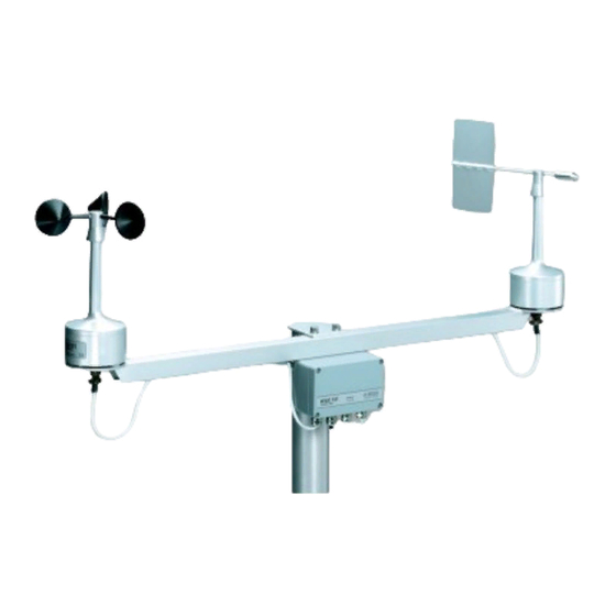
Page 7: Product Overview
The WAC151 cross arm assembly supports the installation of: • Vaisala Anemometer WAA151 and Vaisala Wind Vane WAV151 • Vaisala Heated Anemometer WAA252 and Vaisala Heated Wind Vane WAV252 The cross arm assembly consists of a junction box and an anodized aluminum tube with a mounting clamp for installation on the top of a pole mast. -
Page 8: Esd Protection
Any modification voids your warranty. 2.2.1 ESD protection Electrostatic Discharge (ESD) can damage electronic circuits. Vaisala products are adequately protected against ESD for their intended use. However, it is possible to damage the product by delivering electrostatic discharges when touching, removing, or inserting any objects in the equipment housing. -
Page 9: Installation
Additional protection is needed in regions with frequent, severe thunderstorms, especially when long line cables (>30 m (98 ft)) are used. Vaisala recommends using a surge protector, such as WSP150, in all sites with an elevated risk of a lightning strike. - Page 10 WAC151 User Guide M210349EN-C Figure 1 Recommended mast location in open area Any object of height (h) does not remarkably disturb wind measurement at a minimum distance of 10 × h. There must be at least 150 m (500 ft) open area in all directions from the mast.
-
Page 11: Installing Cross Arm Wac151
1.5 times the height of the building (H). When the diagonal (W) is less than the height (H) the minimum length of the mast is 1.5 × W. 3.2 Installing Cross Arm WAC151 If you install the equipment in tropical, marine, or cold environments, keep the equipment within its specific operating conditions. - Page 12 WAC151 User Guide M210349EN-C • Cable cutters • Cable stripper • Slothead screwdriver 1. Remove the four screws holding the cover of the junction box. Remove the cover. 2. Lead the sensor cable through the cable gland. 3. For better protection against RF interference, fold the braided cable shield over the plastic sleeve.
- Page 13 Chapter 3 – Installation 7. Attach the cross arm to the top of the pole mast with the mounting clamp.
-
Page 14: Connecting Wind Sensors
Cross arm WAC151 Connector Mounting flange South North 3.3 Connecting wind sensors The cables for wind sensors WAA151 and WAV151 are connected in the factory. If you install wind sensors WAA252 and WAV252, change the connections in the WAC151 junction box. -
Page 15: Wiring Wind Sensors Waa151 And Wav151
Figure 3 Wiring diagram for WAA151 and WAV151 installed on WAC151 3.3.2 Wiring wind sensors WAA252 and WAV252 If you use the standard power and signal cables ZZ45049 and ZZ45048, follow these instructions. -
Page 16: Mounting Wind Set On Mast
M210349EN-C 3. For the optional sensor power input, connect BRN to the terminal #6. Vaisala recommends using Vaisala WHP25 Mains Power Supply as a power source. It has a mast mountable, all-weather enclosure. WHP25 is sold only as a spare part. - Page 17 Chapter 3 – Installation 1. Place the cross arm on the mast. 2. Tighten the bolts. Tightening torque 5 Nm. 3. Align the wind set.
-
Page 18: Aligning Wind Set
WAC151 User Guide M210349EN-C Figure 5 WA15 installed on top of mast 3.5 Aligning wind set • Compass The mast must be erected before aligning. - Page 19 Chapter 3 – Installation 1. To align the wind set on a mast, use a compass or other similar method to make sure that the wind vane end of the cross arm is pointing to the North. 2. Connect the sensor cable.
-
Page 20: Maintenance
WAC151 User Guide M210349EN-C 4. Maintenance 4.1 Visual checking Every 1 to 2 years, check that the component board is not corroded. A probable cause for corrosion may be that the box cover or cable gland have not been tightened properly. -
Page 21: Troubleshooting
The data collection system Improper or loose connections. Check the wiring and tighten does not receive data. the screw terminals. Shaft heating of WAC151 and Improper or loose connections. Check the wiring and tighten WAV151 is not working. the screw terminals. -
Page 22: Technical Data
WAC151 User Guide M210349EN-C 6. Technical data 6.1 WAC151 specifications Table 4 WAC151 cross arm specifications Property Description / Value I/O connectors 15 screw terminal connectors for sensors and power lines Cable entries Signal cable Through a gland (for cable diameter 7 ... 10 mm) -
Page 23: Technical Support
Please see the applicable supply contract or Conditions of Sale for details of the warranty for each product. 1. Read the warranty information. 2. Contact Vaisala technical support and request a Return Material Authorization (RMA) and shipping instructions. Always request the RMA before returning any faulty material. - Page 26 www. v aisala.com...
Need help?
Do you have a question about the WAC151 and is the answer not in the manual?
Questions and answers