Beyerdynamic Stegos Operating Instructions Manual
Wireless digital boundary microphone system
Hide thumbs
Also See for Stegos:
- Features and specifications (4 pages) ,
- Quick start manual (32 pages)
Table of Contents
Advertisement
Advertisement
Table of Contents

Related Manuals for Beyerdynamic Stegos


Summary of Contents for Beyerdynamic Stegos
- Page 1 OPERATING INSTRUCTIONS Stegos Wireless digital Boundary Microphone System...
-
Page 3: Table Of Contents
Stegos RS receiver ..........4 Stegos TB boundary microphone ....... . . 6 Disposal . -
Page 4: Safety And Environment
The wireless Stegos system includes receiver and boundary microphone and has been developed especially for the use with video conference systems. Up to three Stegos systems can be operated in neighbouring rooms simultaneously. - Page 5 • If you connect defective or unsuitable accessories, the equipment could be damaged. Only use connection cables available from or recommended by beyerdynamic. If you use cables you have made up yourself, all claim to warranty is null and void.
-
Page 6: Stegos Tb Boundary Microphone
Stegos – Safety and Environment Stegos TB boundary microphone • Protect the boundary microphone from moisture and sudden impacts. You could either injure yourself or others or damage the microphone. • Never take batteries apart yourself. The battery acid contained will damage skin and clothing. -
Page 7: Stegos Rs Receiver
Stegos – RS Receiver Stegos RS receiver The receiver provides three different connections for video conference systems: 3-pin Phoenix terminal strip, mini jack (3.5 mm) and 3-pin XLR. The individual microphone signals are available via a multipin Phoenix terminal strip. For the data exchange with media control systems or PC there is an RS 232 interface and a USB connection available. -
Page 8: How To Connect The Antennae
• Avoid shadowing effect of the Stegos RS antennae, especially by metallic surfaces. • A free line of sight between the Stegos RS receiver and the Stegos TB microphone is ideal. Big obstacles in between can possibly affect the radio transmission. In such specific installations the use of remote antennae can possibly achieve an improvement of the RF situation. -
Page 9: How To Operate The Receiver
LED will illuminate. • The channel LEDs 1 to 4 will illuminate green to indicate the availability. As soon as you turn on the first Stegos TB boundary microphone, the channel LED 1 will illuminate red to indicate that the channel is occupied. -
Page 10: How To Install A Receiver Into A 19" Rack
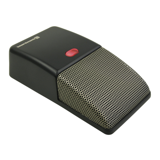
Stegos – TB Boundary Microphone How to install a receiver into a 19" rack • If you want to install a receiver into a 19" rack, mount the supplied brackets to the right and left hand side. Mounting bracket Mounting bracket Stegos TB boundary microphone The boundary microphone provides a semi-cardioid polar pattern with a high gain before feedback. -
Page 11: How To Operate The Microphone
Stegos – TB Boundary Microphone How to operate the microphone On/Off mode • Turn on the Stegos TB boundary microphone with the push- button . The microphone that is turned on first, is always allocated to channel 1. • The microphone is open and the push-button will illuminate red. -
Page 12: How To Recharge
Select the “Power off” push-button in the Stegos software. How to recharge • Before the Stegos TB boundary microphone is used for the first time, you have to recharge the integrated rechargeable batteries. • In order to recharge the batteries connect the supplied mains charger adapter to the microphone and a power socket. -
Page 13: Mains Operated
Stegos – Software Mains operated • The Stegos TB boundary microphone can also be powered via the supplied mains charger adapter. • Connect the mains charger adapter to the DC socket . The LED will illuminate briefly for once, afterwards the LED will permanently illuminate green. -
Page 14: Putting Into Operation
• Turn on the Stegos TB boundary microphones by pressing the push-button • Start the software. • When the Stegos RS receiver is connected to the RS 232 interface of your PC, select under “Connectivity Settings” in the “Settings” menue the appropriate “Com” port and then select “System Connect”. -
Page 15: Main Menu
“Global Mute” means that when one microphone is muted via the push-button , the other Stegos TB boundary microphones in the room are also muted. • With the “Power Off” button you can turn off the turned on Stegos TB boundary microphones. -
Page 16: Settings
Stegos – Software Settings Connectivity Settings • Depending if you have connected the Stegos RS receiver to the USB port or RS 232 interface, you can select the appropriate Com port. • When you have selected the Com port, select “Connect”. -
Page 17: Maintenance
Stegos – Software Software Programmer • In the Software Programmer area you can update the firmware of the Stegos receiver and the boundary microphones. • If you would like to update the firmware of the receiver, select the “Select File” button, select the appropriate file and then select the “Start Update”... -
Page 18: Trouble Shooting
Simultaneous operation of the Stegos system and other 2.4 GHz devices (e.g. WLAN, Bluetooth) Physical laws Due to many physical laws it is not possible to guarantee a simultaneous interference-free operation of different devices using the same frequency band. -
Page 19: Stegos And Wlan Or Wifi
Stegos and WLAN or WiFi Like WLAN, the Stegos system uses the same bandwidth of approx. 22 MHz for each RF channel (Low, Mid, High). This results in three compatible RF channels in the 2.4 GHz-ISM band. These are theoretically:... -
Page 20: Stegos And Bluetooth
Stegos system. Due to this frequency compatibility the Stegos system is operated WLAN- friendly. Due to careful frequency planning it is possible to operate one Stegos receiver and a maximum of two WLAN devices nearby simultaneously. More tips for installation •... -
Page 21: Components
Digital diversity receiver, 4 channels, 19" metal housing, 1 U, 128bit digital encryption, RS 232, USB port, with Stegos software and 2 x CA 2411 angled rod antennae..Order # 721.379 Technical specifications General Frequency range . - Page 22 Stegos – Technical Specifications Stegos RS receiver Connections (on the rear) Balanced, per channel (+6 dBu) ..Phoenix terminals (4x3) Balanced, Mix Signal (+6 dBu/-10dB switchable) ... Phoenix terminals / XLR (male) / mini jack (3.5 mm) Monitor headphone output .
-
Page 23: Notes On The Pin Assignment Of The Audio Outputs
Notes on the pin assignment of the audio outputs All connections on the rear of the Stegos RS receiver are balanced outputs. For the pin assignment of the outputs please refer to the following illustrations. They can directly be connected only to appropriate balanced inputs, such as video conference systems. -
Page 24: Dimensions
Stegos – Technical Specifications 10.2 Dimensions Stegos RS receiver All dimensions in mm and [inch]... - Page 25 Stegos – Technical Specifications Stegos TB boundary microphone All dimensions in mm and [inch]...
-
Page 26: Examples Of Use
3-pin Phoenix terminal strip of the video conference system may differ from the Phoenix connector of the Stegos RS receiver. When connecting, please make sure that you connect of both devices ground to ground, “+” to “+” and “-” to “-”. -
Page 27: How To Connect Stegos To A Video Conference System Via The Mini Jack Connector To Phono Rca (Unbalanced)
How to connect Stegos to a video conference system via the mini jack connector to phono RCA (unbalanced) You can connect the 3-pole mini jack connection of the Stegos RS receiver to the AUDIO IN (LINE) RCA phono connector of a video conference system e.g. Sony ®... -
Page 28: How To Connect Stegos To A Video Conference System Via The Mini Jack Connector To Mini Jack Connector (Balanced)
(balanced) You can connect the 3-pole mini jack connection of the Stegos RS receiver to the balanced mini jack connection (3.5 mm) of a video conference system with identical pin assignment e.g. Aethra ®... -
Page 29: How To Connect Stegos To A Pc Sound Card Via The Mini Jack Connector To Mini Jack Connector (Unbalanced)
• Connect another mono mini jack (3.5mm)/RCA phono adaptor to the LINE connection (mini jack 3.5 mm) of the PC sound card. • Connect one end of the RCA phono/RCA phone cable to the adaptor of the Stegos RS receiver and the other end to the adaptor of the PC sound card. -
Page 30: Frequently Asked Questions
• the volume and mute settings in the Stegos software. • furthermore, the position of the Mix output switch of the Stegos RS receiver: – the Mix output switch is set to -10 dB and must be set to 0 dB in this case. -
Page 31: Ec-Declaration Of Conformity
Theresienstrasse 8, 74072 Heilbronn, Germany Type of Equipment: Digital Wireless Microphone System Model Number/s: Stegos TB, Stegos RS I, the undersigned, as an employee of beyerdynamic, hereby declare that the equipment specified conforms to the above Directive and Standards. Manufacturer’s Signature: Date: August 1... -
Page 32: Fcc-Regulation
Stegos – FCC Regulation FCC Regulation FCC ID: OSDSTEGOSTB for Stegos TB FCC ID: OSDSTEGOSRS for Stegos RS Canada: IC: 3628A-STEGOSTB for Stegos TB Canada: IC: 3628A-STEGOSRS for Stegos RS Part 15.19 Statement NOTICE: This device complies with Part 15 of the FCC Rules [and with RSS-210 of Industry Canada]. - Page 34 GmbH & Co. KG Theresienstr. 8 | 74072 Heilbronn – Germany Tel. +49 (0) 7131 / 617 - 0 | Fax +49 (0) 7131 / 617 - 204 info@beyerdynamic.de | www.beyerdynamic.com For further distributors worldwide, please go to www.beyerdynamic.com...
Need help?
Do you have a question about the Stegos and is the answer not in the manual?
Questions and answers