
Related Manuals for Beyerdynamic Opus 900


Summary of Contents for Beyerdynamic Opus 900
- Page 1 BEDIENUNGSANLEITUNG OPERATING INSTRUCTIONS NOTICE D’UTILISATION MANUAL DEL USUARIO Opus 900 Drahtloses UHF-System Wireless UHF System Système sans fil UHF Sistema inalámbrico en UHF...
-
Page 2: Table Of Contents
Konformitätserklärung ..... . Seite 140 OPERATING INSTRUCTIONS Opus 900 Important Safety Information ....Page NE 900 Diversity Receiver . -
Page 3: Service
OPERATING INSTRUCTIONS OPUS 900 Thank you for selecting the Opus 900 wireless system. Please take some time to read carefully through this manual before setting up the equipment. Important: • When you unpack the product, inspect it for transport damage. If you do find transport damage, notify the transportation company without delay. - Page 4 • Lay all connection cables so that they do not present a trip hazard. • Check whether the connection figures comply with the existing mains supply. Serious damage could occur due to connecting the system to the wrong power supply. An incorrect mains voltage could damage the equipment or cause an electric shock.
- Page 5 • Consult the dealer or an experienced radio/TV technician for help. In accordance with FCC requirements, changes or modifications not expressly approved by beyerdynamic GmbH & Co. KG could void the user’s authority to operate this product. Any changes or modifications not expressly approved by the party responsible for compliance...
-
Page 6: Ne 900 Diversity Receiver
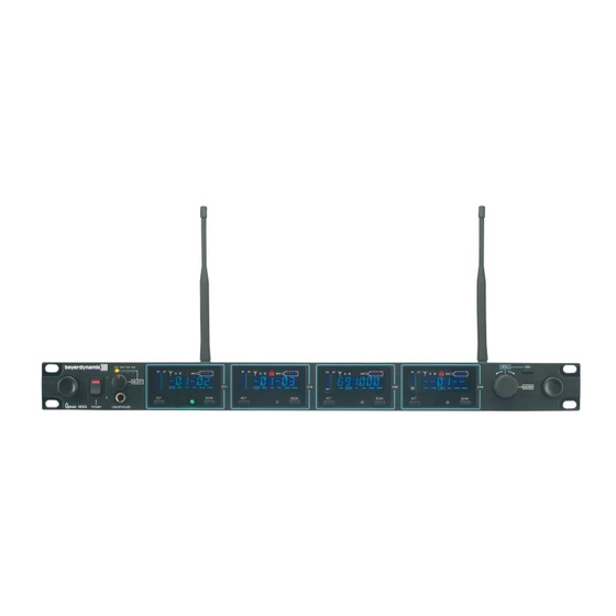
NE 900 Diversity Receiver Controls and Indicators NE 900 S front view NE 900 D front view NE 900 Q front view Power switch with LED indicator Headphone input Volume control for headphone input to listen to individual receiving channels NE 900 D / Q: Press the volume control to select the receiving channel Display ACT button... - Page 7 NE 900 S rear view NE 900 D rear view NE 900 Q rear view Antenna input B. TNC socket. With power supply for antenna amplifier. AF output, 3-pin XLR, balanced Remote connection IN / OUT Antenna input A. TNC socket. With power supply for antenna amplifier. Mains NE 900 S only: AF output, 1/4"...
- Page 8 How to connect the Antennae Connect the antennae to the TNC sockets and ( . Set them at an angle (60°). Please note that for diversity operation both antennae have to be connected. A weighting circuit silently switches the signal with the better S/N ratio to the output. Setting up 1.
- Page 9 1.4.2 How to read the AF- and RF-level The AF- or RF- level is shown in the LC-display. 1.4.3 Group, Channel • Turn the menu control to select “G/CH”. The currently selected group and channel are displayed. • To change the setting, press the menu control. The group number will start flashing. Turn the menu control to select the desired group.
- Page 10 1.4.5 Squelch • Turn the menu control to select “SQ”. The currently selected squelch is displayed. • To change the squelch level, press the menu control. The squelch level will start to flash. Turn the menu control to select the desired squelch level between 1 and 99. In order to confirm the selected squelch level, press the menu control.
- Page 11 1.4.7 Name • Turn the menu control to select “NAME”. A stored name is displayed or you can enter a new name. • To enter a new name press the menu control. The first digit will start to flash. Turn the menu control to select the desired letter, number or character.
-
Page 12: Lock Function
1.4.9 Lock Function The receivers have a lock function to avoid the setting of the receiver configuration to be changed inadvertently. How to activate the “Lock” Function • Press the ACT and Scan buttons simultaneously. • A red padlocked symbol is displayed. •... - Page 13 Connecting and Positioning of remote Antennae In multichannel systems we recommend the use of the AT 70 A/B UHF antenna set consisting of antennae, cables, antenna boosters and mounting kit. 1. Connect the receiving antennae to the corresponding antenna inputs and place the antennae to the right and left of the receiver in the operating range where the transmitter is to be used.
-
Page 14: Zas 800 Antenna Splitter
ZAS 800 Antenna Splitter 1.7.1 Controls and Indicators (1) On/Off switch and power on LED. When the antenna splitter is switched on, the red LED will illuminate. (2) RF outputs to connect the receivers (3) DC-connection to connect the DC power supply unit (12 V) (4) Antenna sockets A/B. -
Page 15: General Information
4. Connect the power supply unit to the DC-connection (3) and to AC power. (Attention: Make sure that the indicated voltage corresponds to the local voltage.) 5. Switch on the ZAS 800 antenna splitter (1). 1.7.3 General Information 1. The antenna sockets (4) feature a voltage of 8 V DC bias. To avoid a short circuit the sockets must not touch the rack housing. -
Page 16: Connection To A Pc
Connection to a PC The NE 900 receiver is fitted with an RJ 11 connector with an IN and Out socket. In order to operate several receivers with a PC they have to be connected as described below. • Connect the OUT-socket of the first receiver (RX 1) with the IN-socket of the second receiver (RX 2), connect the OUT-socket of the second receiver (RX 2) with the IN-socket of the third receiver (RX 3) and so on. -
Page 17: S 900 Handheld Transmitters
S 900 Handheld Transmitter Controls and Indicators There are different condenser and dynamic microphone capsules for the handheld transmitter (refer to Optional Accessories). The S 900 C handheld transmitter has charging contacts and can be operated with the integrated rechargeable battery pack only. Avoid a direct contact of the charging contacts to the skin, as there is a voltage of 3 V at maximum. - Page 18 2. Insert two 1.5 V batteries into the battery compartment observing polarity markings. Note: The S 900 C transmitter is powered by rechargeable batteries which cannot be changed by the user. If the rechargeable batteries have to be changed, please contact your beyerdynamic dealer. 2.3 LC-Display 1.
- Page 19 2.4 Battery Status • When the battery is exhausted, the LED at the bottom of the handheld transmitter will illuminate. Replace the battery. When “PoFF“ is displayed, the transmitter is switched off, if the battery voltage is too low. How to switch off the Handheld Transmitter When the ON/OFF switch at the bottom of the transmitter is switched to “OFF“, at first “PoFF“...
- Page 20 DM 969 Supercardioid dynamic microphone capsule. Suitable for vocals. Weight 131 g. EM 981 Cardioid electret condenser microphone capsule for solo vocals, conferences and speech. Weight 191 g. Maintenance • Protect the handheld transmitter from humidity, knocks and shock. Avoid dropping the transmitter at all times.
- Page 21 DM 960 • Unscrew the upper part of the microphone basket (turn anti- clockwise). • Clean it under clear water. • Let the pop shield dry overnight before you replace it. • The upper part of the microphone basket cannot be cleaned in a dishwasher.
- Page 22 How to adjust the Gain • To adjust the gain unscrew the complete microphone head with the upper shaft as indicated by the arrows. • Use a screwdriver to select the gain (0 dB, 10 dB, 20 dB, 30 dB). •...
-
Page 23: Ts 900 Beltpack Transmitter
TS 900 Beltpack Transmitter The TS 900 C beltpack transmitter provides charging contacts and can be powered by rechargeable batteries as well. Controls and Indicators TS 900 C AF input, 4-pin mini XLR for microphones (lavalier, neckworn mics). For connection please refer to chapter 3.5 “AF Connection”. ON/OFF switch (ON = switch to “ON“-position;... - Page 24 TS 900 M AF input, 4-pin mini XLR for microphones (lavalier, neckworn mics). For connection please refer to chapter 3.5 “AF Connection”. ON/OFF switch (ON = switch to “ON“-position; OFF = switch to “OFF“ position). Switch off the transmitter when not in use. Transmitting antenna LC-Display Infrared receiving diode for ACT function.
- Page 25 This is how to remove the belt clip How to insert the Batteries / rechargeable Battery Pack 1. Push down the two snap locks on the right and left of the battery compartment and open it. Remove the batteries. Refer to Fig. 1. 2.
- Page 26 Setting up 1. Push down the two snap locks on the right and left of the battery compartment and open it. Now you can adjust the GT/MT switch and the gain control 2. Make sure that the transmitter and receiver are on the same frequency. 3.
- Page 27 AF Connection 2-Wire Electret Condenser Microphone Capsule e.g. MCE 5.18, MCE 10.18, MCE 60.18 3-Wire Electret Condenser Microphone Capsule e.g. Opus 54.18, Opus 55.18, Opus 56.18, MCE 7.18 Dynamic Microphone Electric Guitar Line-in (impedance 8Ω, attenuation 10 dB)
- Page 28 LC-Display 1. “ERR“ Message: When the “ERR“ message is displayed, there is an error. ERR noo3: The frequency you want to program is above the switching bandwidth of the transmitter. Use a receiver with an appropriate frequency group. (At this time the micro- phone is still operating and the frequency remains unchanged.
-
Page 29: General Instructions For All Transmitters
The interference is possibly eliminated by changing the squelch (refer also to chapter 1.4.5 “Squelch”. When using multi-channel-systems, please contact beyerdynamic. Interferences can also be caused by DVB-T television transmitters in the neighbourhood. What to Do to avoid Feedback Feedback is caused by your microphone getting too close to a loudspeaker. -
Page 30: Trouble Shooting
Trouble Shooting NE 900 Diversity Receiver Problem Possible Cause Solution • Connect the receiver to AC power No function • Power supply is interrupted, power supply unit is not connected to the mains and / or to receiver No reception •... -
Page 31: Maintenance
In most countries around the world, wireless systems must be approved for use by the authorities and it may be necessary to obtain a licence to use it legally. Your local beyerdynamic dealer will be able to give you details on wireless system regulations for your area. -
Page 32: Optional Accessories
SDM 969 UHF handheld transmitter, plastic housing, DM 969 microphone capsule, 668 - 692 MHz ... . . Order # 490.229 SDM 969 same as above, but 774 - 798 MHz..... . Order # 490.237 SDM 969 same as above, but 790 - 814 MHz*. -
Page 33: Technical Specifications
Opus 900 CD-ROM ........Order # 490.792... - Page 34 Sensitivity ..... . . 2 µV Antenna connection ....2 x TNC Nominal deviation .
- Page 35 TS 900 (C / M) Beltpack Transmitter Frequency range ....668 - 692 MHz 774 - 798 MHz 790 - 814 MHz* 841 - 865 MHz* Modulation .
- Page 36 Model Number/s: Transmitters S 900, S 900 C, S 900 M, TS 900, TS 900 M I, the undersigned, as an employee of beyerdynamic, hereby declare that the equipment specified conforms to the above Directive and Standards. Manufacturer’s Signature: Date:...
- Page 37 Wireless Microphone System Opus 900 Model Number/s: Receivers NE 900 D, NE 900 Q, NE 900 S I, the undersigned, as an employee of beyerdynamic, hereby declare that the equipment specified conforms to the above Directive and Standards. Manufacturer’s Signature:...
- Page 38 GmbH & Co. KG Theresienstr. 8 D-74072 Heilbronn, Germany Tel. +49 (0 )71 31 / 6 17-0 Fax +49 (0 )71 31 / 617-224 E-mail: info@beyerdynamic.de Internet: www.beyerdynamic.de beyerdynamic U.K. Ltd. 17 Albert Drive Burgess Hill RH15 9TN Tel. +44 (0)1444 / 258 258 Fax +44 (0)1444 / 258 444 E-mail: sales@beyerdynamic.co.uk...
Need help?
Do you have a question about the Opus 900 and is the answer not in the manual?
Questions and answers