Table of Contents
Advertisement
Advertisement
Table of Contents

Related Manuals for Beyerdynamic Opus 910


Summary of Contents for Beyerdynamic Opus 910
- Page 1 OPERATING INSTRUCTIONS Opus 910 Wireless UHF System...
-
Page 3: Table Of Contents
CONTENTS OPERATING INSTRUCTIONS Opus 910 Important Safety Information ....Page NE 911 / 912 / 914 Diversity Receiver ... . . Page ZAS 900 Antenna Splitter . -
Page 4: Operating Instructions Opus
OPERATING INSTRUCTIONS OPUS 910 Thank you for selecting the Opus 910 wireless system. Please take some time to read carefully through this manual before setting up the equipment. Important: • When you unpack the product, inspect it for transport damage. If you do find transport damage, notify the transportation company without delay. - Page 5 • This equipment needs adequate ventilation. Do not cover ventilation grilles. If the heat it generates cannot be dissipated, the equipment could be damaged or flammable materials in its immediate vicinity could be ignited. Take care to ensure that the air can circulate freely through the ventilation grilles and keep flammable materials away.
- Page 6 NOTICE: Changes or modifications made to this equipment not expressly approved by beyerdynamic GmbH & Co. KG may void the FCC authorization to operate this equipment. NOTICE: This device complies with Part 15 of the FCC Rules and with RSS-210 of Industry Canada.
- Page 7 CONSUMER ALERT Most users do not need a license to operate this wireless microphone system. Nevertheless, operating this microphone system without a license is subject to certain restrictions: the system may not cause harmful interference; it must operate at a low power level (not in excess of 50 milliwatts); and it has no protection from interference received from any other device.
-
Page 8: Ne 911 / 912 / 914 Diversity Receiver
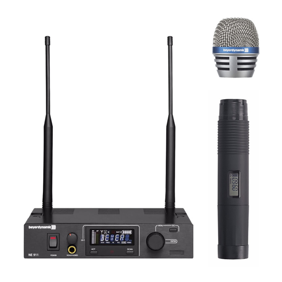
NE 911 / 912 / 914 Diversity Receiver Controls and Indicators NE 911 front view NE 912 front view NE 914 front view Power switch with LED indicator Headphone input Volume control for headphone input to listen to individual receiving channels NE 912 / 914: Press the volume control to select the receiving channel Display ACT button... - Page 9 NE 911 rear view NE 912 rear view NE 914 rear view Antenna input B. TNC socket. With power supply for antenna amplifier. AF output, 3-pin XLR, balanced Remote connection IN / OUT Antenna input A. TNC socket. With power supply for antenna amplifier. Mains NE 911 only: AF output, 1/4"...
- Page 10 How to connect the Antennae Connect the antennae to the TNC sockets and ( . Set them at an angle (60°). Please note that for diversity operation both antennae have to be connected. A weighting circuit silently switches the signal with the better S/N ratio to the output. Setting up 1.
- Page 11 1.4.2 How to read the AF and RF level The AF or RF level is shown in the LC-display. 1.4.3 Group, Channel • Turn the menu control to select “G/CH”. The currently selected group and channel are displayed. • To change the setting, press the menu control. The group number will start flashing. Turn the menu control to select the desired group.
- Page 12 1.4.5 Squelch • Turn the menu control to select “SQ”. The currently selected squelch is displayed. • To change the squelch level, press the menu control. The squelch level will start to flash. Turn the menu control to select the desired squelch level between 1 and 99. In order to confirm the selected squelch level, press the menu control.
- Page 13 1.4.7 Name • Turn the menu control to select “NAME”. A stored name is displayed or you can enter a new name. • To enter a new name press the menu control. The first digit will start to flash. Turn the menu control to select the desired letter, number or character.
-
Page 14: Lock Function
1.4.9 Lock Function The receivers have a lock function to avoid the setting of the receiver configuration to be changed inadvertently. How to activate the “Lock” Function • Press the ACT and Scan buttons simultaneously. • A red padlocked symbol is displayed. •... - Page 15 Connecting and Positioning of remote Antennae In multichannel systems we recommend the use of the AT 70 A/B UHF antenna set consisting of antennae, cables, antenna boosters and mounting kit. 1. Connect the receiving antennae to the corresponding antenna inputs and place the antennae to the right and left of the receiver in the operating range where the transmitter is to be used.
-
Page 16: Zas 900 Antenna Splitter
ZAS 900 Antenna Splitter 1.7.1 Controls and Indicators (1) On/Off switch and power on LED. When the antenna splitter is switched on, the red LED will illuminate. (2) RF outputs to connect the receivers (3) DC-connection to connect the DC power supply unit (12 V) (4) Antenna sockets A/B. -
Page 17: General Information
1.7.3 General Information 1. The antenna sockets (4) feature a voltage of 8 V DC bias. To avoid a short circuit the sockets must not touch the rack housing. 2. For the connection of remote antennae use usual 50Ω coaxial cables. The longer the cable, the higher the RF signal loss. -
Page 18: Connection To A Pc
Connection to a PC The NE 911/912/914 receiver is fitted with an RJ 11 connector with an IN and OUT socket. In order to operate several receivers with a PC they have to be connected as described below. • Connect the OUT-socket of the first receiver (RX 1) with the IN-socket of the second receiver (RX 2), connect the OUT-socket of the second receiver (RX 2) with the IN-socket of the third receiver (RX 3) and so on. -
Page 19: S 910 C / S 910 M Handheld Transmitters
S 910 C / S 910 M Handheld Transmitter Controls and Indicators There are different condenser and dynamic microphone capsules for the handheld transmitter (refer to Optional Accessories). The S 910 C handheld transmitter has charging contacts and can be operated with the integrated rechargeable battery pack only. - Page 20 Note: The S 910 C transmitter is powered by rechargeable batteries which cannot be changed by the user. If the rechargeable batteries have to be changed, please contact your beyerdynamic dealer. LC-Display 1. “ERR“ Message: When the “ERR“ message is displayed, there is an error.
- Page 21 Battery Status • When the battery is exhausted, the LED at the bottom of the handheld transmitter will illuminate. Replace the battery. When “PoFF“ is displayed, the transmitter is switched off, if the battery voltage is too low. How to switch off the Handheld Transmitter When the ON/OFF switch at the bottom of the transmitter is switched to “OFF“, at first “PoFF“...
- Page 22 DM 969 Supercardioid dynamic microphone capsule. Suitable for vocals. Weight 131 g. EM 981 Cardioid electret condenser microphone capsule for solo vocals, conferences and speech. Weight 191 g. RM 510 Cardioid dynamic ribbon microphone head. Weight 165 g.
- Page 23 Maintenance • Protect the handheld transmitter from humidity, knocks and shock. Avoid dropping the transmitter at all times. • For cleaning metal surfaces, use a soft cloth moistened with methylated spirits or alcohol. • As soon as your microphone sounds dull, you should clean the integrated pop shield. Proceed as described in the following.
- Page 24 DM 969 • Unscrew the upper part of the microphone basket (turn anti-clockwise). • Pull out the foam pop shield and clean it under clear running water. • If necessary, use a mild washing-up liquid. • Dry it afterwards with a hairdryer or allow it to dry overnight. •...
- Page 25 How to adjust the Gain • To adjust the gain unscrew the complete microphone head with the upper shaft as indicated by the arrows. • Use a screwdriver to select the gain (0 dB, 10 dB, 20 dB, 30 dB). •...
-
Page 26: Ts 910 Beltpack Transmitter
The TS 910 C beltpack transmitter provides charging contacts and can be powered by the optional beyerdynamic TS 900 AP rechargeable battery pack. For charging, the SLG 900 charger is available. With this charger the TS 900 AP battery pack inside the TS 910 C beltpack transmitter can be recharged only, no standard rechargeable batteries. - Page 27 TS 910 M TS 910 M AF input, 4-pin mini XLR for microphones (lavalier, neckworn mics). For connection please refer to chapter 3.5 “AF Connection”. ON/OFF switch (ON = switch to “ON“-position; OFF = switch to “OFF“ position). Switch off the transmitter when not in use. Transmitting antenna LC-Display Infrared receiving diode for ACT function.
- Page 28 This is how to remove the belt clip How to insert the Batteries / rechargeable Battery Pack 1. Push down the two snap locks on the right and left of the battery compartment and open it. Remove the batteries. Refer to Fig. 1. 2.
- Page 29 Setting up 1. Push down the two snap locks on the right and left of the battery compartment and open it. Now you can adjust the GT/MT switch and the gain control 2. Make sure that the transmitter and receiver are on the same frequency. 3.
- Page 30 AF Connection 2-Wire Electret Condenser Microphone Capsule e.g. MCE 5.18, MCE 10.18, MCE 60.18 3-Wire Electret Condenser Microphone Capsule e.g. Opus 54.18, Opus 55.18, Opus 56.18, MCE 7.18 Dynamic Microphone Electric Guitar Line-in (impedance 8Ω, attenuation 10 dB)
- Page 31 LC-Display 1. “ERR“ Message: When the “ERR“ message is displayed, there is an error. ERR noo3: The frequency you want to program is above the switching bandwidth of the transmitter. Use a receiver with an appropriate frequency group. (At this time the microphone is still operating and the frequency remains unchanged.
-
Page 32: General Instructions For All Transmitters
The interference is possibly eliminated by changing the squelch (refer also to chapter 1.4.5 “Squelch”. When using multi-channel-systems, please contact beyerdynamic. Interferences can also be caused by DVB-T television transmitters in the neighbourhood. What to Do to avoid Feedback Feedback is caused by your microphone getting too close to a loudspeaker. -
Page 33: Trouble Shooting
Trouble Shooting NE 911 / 912 / 914 Diversity Receiver Problem Possible Cause Solution • Connect the receiver to AC power No function • Power supply is interrupted, power supply unit is not connected to the mains and / or to receiver No reception •... -
Page 34: Maintenance
In most countries around the world, wireless systems must be approved for use by the authorities and it may be necessary to obtain a licence to use it legally. Your local beyerdynamic dealer will be able to give you details on wireless system regulations for your area. -
Page 35: Optional Accessories
CD ROM Opus 910 CD-ROM........Order # 490.792... -
Page 36: Technical Specifications
DM 969 S Dynamic, supercardioid, silver ......Order # 490.512 EM 981 S Electret condenser, cardioid, silver ..... . . Order # 490.520 RM 510 Ribbon, dynamic, cardioid, silver . - Page 37 S 910 (M / C) + CM 930 / DM 960 / DM 969 / RM 510 / EM 981 Handheld Transmitter Polar pattern ..... Hypercardioid (S 910 + DM 960) Supercardioid (S 910 + DM 969) Cardioid (S 910 + RM 510, S 901 + EM 981, S 910 + CM 930) Transducer type .
- Page 38 TS 910 (C / M) Beltpack Transmitter Frequency range....482 – 518 MHz (US) 518 – 554 MHz (US) 554 – 590 MHz (US) 590 –...
- Page 40 GmbH & Co. KG Theresienstr. 8 | 74072 Heilbronn – Germany Tel. +49 (0) 7131 / 617 - 0 | Fax +49 (0) 7131 / 617 - 204 info@beyerdynamic.de | www.beyerdynamic.com For further distributors worldwide, please go to www.beyerdynamic.com...
Need help?
Do you have a question about the Opus 910 and is the answer not in the manual?
Questions and answers