Beyerdynamic Opus 600 Operating Instructions Manual
Wireless microphone system
Hide thumbs
Also See for Opus 600:
- Operating instructions manual (124 pages) ,
- Operating instructions manual (148 pages)

Related Manuals for Beyerdynamic Opus 600


Summary of Contents for Beyerdynamic Opus 600
-
Page 1: Manual Del Usuario
BEDIENUNGSANLEITUNG OPERATING INSTRUCTIONS NOTICE D’UTILISATION MANUAL DEL USUARIO Opus 600 Drahtloses Mikrofonsystem Wireless Microphone System Système de microphone sans fil Sistema inalámbrico... -
Page 2: Table Of Contents
Opus 600 – Contents Safety and environment ......... . . 34 NE 600 diversity receiver . -
Page 3: Safety And Environment
Opus 600 – Safety and Environment Thank you for selecting the Opus 600 wireless system. Please take some time to read carefully through this manual before setting up the equipment. Important: • When you unpack the product, inspect it for transport damage. If you do find transport damage, notify the transportation company without delay. - Page 4 Opus 600 – Safety and Environment Location • The equipment must be set up so that the mains switch, mains plug and all connections on the rear of the device are easily accessible. • If you transport the equipment to another location take care to ensure that it is adequately secured and can never be damaged by being dropped or by impacts on the equipment.
-
Page 5: S 600 / Ts 600 Transmitters
• If you connect defective or unsuitable accessories, the equipment could be damaged. Only use connection cables available from or recommended by beyerdynamic. If you use cables you have made up yourself, all claim to warranty is null and void. - Page 6 • Consult the dealer or an experienced radio/TV technician for help. NOTICE: Changes or modifications made to this equipment not expressly approved by beyerdynamic GmbH & Co. KG may void the FCC authorization to operate this equipment. NOTICE: This device complies with Part 15 of the FCC Rules and with RSS-210 of Industry Canada.
-
Page 7: Ne 600 Diversity Receiver
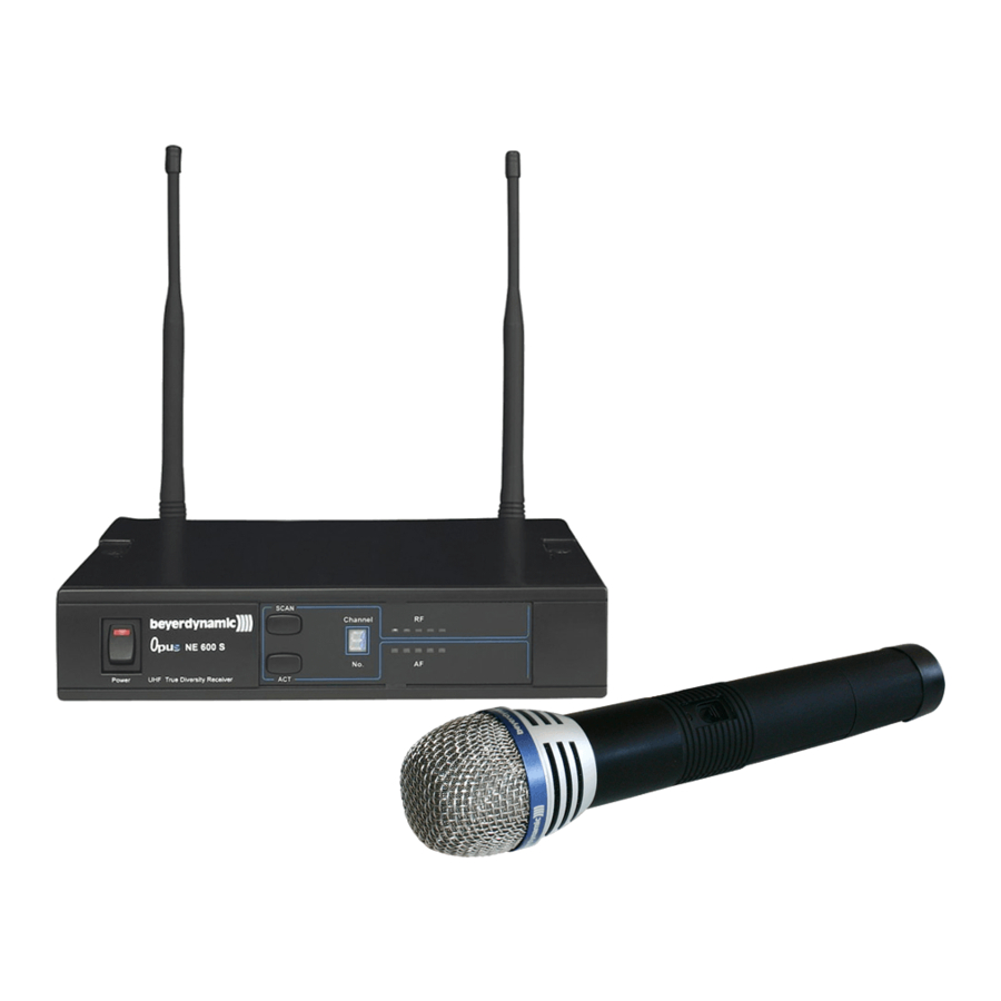
Opus 600 – NE 600 Diversity Receiver NE 600 diversity receiver Controls and indicators Front view – NE 600 S Front view – NE 600 D On-off switch with LED indicator Scan button Channel indicator RF level indicator AF level indicator ACT button 19"... - Page 8 Opus 600 – NE 600 Diversity Receiver Rear view – NE 600 S Rear view – NE 600 D Antenna input B. TNC socket. With power supply for antenna amplifier. Audio output, 3-pin XLR, balanced Mic/Line level switch for audio output .
-
Page 9: How To Connect The Antennae
Opus 600 – NE 600 Diversity Receiver How to connect the antennae Connect the antennae to the TNC sockets and set them at an angle (60°). Please note that for diversity operation both antennae have to be connected. A weighting circuit silently switches the signal with the better S/N ratio to the output. -
Page 10: How To Operate The Receiver
Opus 600 – NE 600 Diversity Receiver • Thread the power cable through the cable grip as shown on the illustration. The cable grip prevents the connector from being pulled off by accident. Cable grip How to operate the receiver •... -
Page 11: Channel / Frequency Selection
Opus 600 – NE 600 Diversity Receiver Channel / frequency selection • The NE 600 provides 16 adjustable frequencies. NE 600 S / D • If you want to change the selected frequency, press the Scan button until the channel indicator will flash. -
Page 12: How To Connect And Position Remote Antennae
Opus 600 – NE 600 Diversity Receiver 2.10 How to connect and position remote antennae In multichannel systems we recommend the use of the AT 70 A/B UHF antenna set consisting of antennae, cables, antenna boosters and mounting kit. 1. Connect the receiving antennae to the corresponding antenna inputs and place the antennae to the right and left of the receiver. -
Page 13: Zas 800 Antenna Splitter
Opus 600 – ZAS 800 Antenna Splitter 2.11 ZAS 800 antenna splitter 2.11.1 Controls and indicators On-off switch and power on LED. When the antenna splitter is switched on, the red LED will illuminate. Outputs to connect the receivers DC-connection to connect the DC power supply unit (12 V) Antenna sockets A/B. -
Page 14: 2.11.3 General Information
Opus 600 – ZAS 800 Antenna Splitter 1. Mount the ZAS 800 antenna splitter and the NE 600 receivers into a 19" rack by using the mounting brackets. 2. Connect the supplied antennae to the antenna sockets A/B . You can also use optional remote antennae. -
Page 15: S 600 Handheld Transmitter
Opus 600 – S 600 Handheld Transmitter S 600 handheld transmitter Controls and indicators There are different condenser and dynamic microphone capsules for the handheld transmitter (refer to chapter 10. Optional accessories). Microphone capsule (can be unscrewed) Battery status indicator... -
Page 16: How To Operate The Handheld Transmitter
Opus 600 – S 600 Handheld Transmitter How to operate the handheld transmitter 1. When the microphone is switched on, the battery status indicator will flash for a moment. 2. As soon as an audio signal is transmitted, the AF meter on the receiver will display a signal. -
Page 17: How To Set The Low-Cut Filter
Opus 600 – S 600 Handheld Transmitter How to set the low-cut filter • The EM 981 microphone capsule features a low-cut filter to compensate the close-miking effect which ususally occurs with directional microphones. To set the low-cut filter unscrew the complete microphone head with the upper shaft as indicated by the arrows. - Page 18 Opus 600 – S 600 Handheld Transmitter DM 969 • Unscrew the upper part of the microphone basket (turn anti-clockwise). • Pull out the foam pop shield and clean it under clear running water. • If necessary, use a mild washing-up liquid.
-
Page 19: Ts 600 Beltpack Transmitter
Opus 600 – TS 600 Beltpack Transmitter TS 600 beltpack transmitter Controls and indicators Transmitting antenna. Battery status LED to indicate the power on-off and battery status. (a) When the beltpack transmitter is switched on this LED will flash for a moment to indicate the normal battery status. -
Page 20: How To Insert The Batteries / Rechargeable Batteries
Opus 600 – TS 600 Beltpack Transmitter GT/MT switch: When you use electric guitars this switch must be in the “GT“ position. In the GT mode the gain control is deactivated. Switch to the “MT“ position when you use condenser and wired microphones. -
Page 21: How To Operate The Beltpack Transmitter
Opus 600 – TS 600 Beltpack Transmitter How to operate the beltpack transmitter 1. Push down the two snap locks on the right and left of the battery compartment and open it. Now you can adjust the GT/MT switch and the gain control 2. -
Page 22: Af Connection
Opus 600 – TS 600 Beltpack Transmitter AF connection 2-wire electret condenser microphone capsule e.g. MCE 5.18, MCE 10.18, MCE 60.18 3-wire electret condenser microphone capsule e.g. Opus 54.18, Opus 55.18 Mk II Dynamic microphone Electric guitar Line-in (impedance 8 Ω, attenuation 10 dB) -
Page 23: General Instructions For All Transmitters
The interference is possibly eliminated by changing the squelch (refer also to chapter 2.6 How to adjust the squelch). When using multi-channel-systems, please contact beyerdynamic. Interferences can also be caused by DVB-T / DVB-H signals or signals of other applications in the UHF range in the neighbourhood. -
Page 24: Trouble Shooting
Opus 600 – Trouble Shooting Trouble shooting NE 600 diversity receiver Problem Possible Cause Solution No function • Power supply is interrupted, • Connect the receiver to receiver is not connected to AC power the mains No reception • Transmitter is not switched •... -
Page 25: Maintenance
In most countries around the world, wireless systems must be approved for use by the authorities and it may be necessary to obtain a licence to use it legally. Your local beyerdynamic dealer will be able to give you details on wireless system regulations for your area. -
Page 26: Optional Accessories
Opus 600 – Optional Accessories Optional accessories NE 600 diversity receiver Antenna splitter ZAS 800 Antenna splitter, active, 19" housing, incl. connecting cables, 506 - 530 MHz ....Order # 497.045 ZAS 800 same as above, but 668 - 692 MHz . -
Page 27: Technical Specifications
Opus 600 – Technical Specifications Technical specifications NE 600 diversity receiver Operating principle ....True diversity receiver (UHF) Frequency range ....506 - 530 MHz... - Page 28 Opus 600 – Technical Specifications Max. SPL......146 dB AF transmission range SDM 660 ......55 - 18,000 Hz (close miking 2 cm) at 80 dB SPL...
-
Page 29: Zas 800 Antenna Splitter
Opus 600 – Technical Specifications ZAS 800 antenna splitter Inputs ......2 x 50 Ω (TNC) Outputs . - Page 30 Receiver for Wireless Microphone System ”Opus 600” Model Number/s: NE 600 S, NE 600 D I, the undersigned, as an employee of beyerdynamic, hereby declare that the equipment specified conforms to the above Directive and Standards. Manufacturer’s Signature: Date: January 21, 2009...
- Page 31 Receiver for Wireless Microphone System ”Opus 600” Model Number/s: S 600, SDM 660, SDM 669, SEM 681, TS 600 I, the undersigned, as an employee of beyerdynamic, hereby declare that the equipment specified conforms to the above Directive and Standards. Manufacturer’s Signature: Date:...
- Page 32 Theresienstr. 8 | 74072 Heilbronn – Germany Tel. +49 (0) 7131 / 617 - 0 | Fax +49 (0) 7131 / 617 - 224 info@beyerdynamic.de | www.beyerdynamic.de Weitere Vertriebspartner weltweit finden Sie unter www.beyerdynamic.de For further distributors worldwide, please go to www.beyerdynamic.com...
Need help?
Do you have a question about the Opus 600 and is the answer not in the manual?
Questions and answers