Table of Contents
Advertisement
Quick Links
aTN VOyaGER 3
aTN VOyaGER 5
voyaGer 3/ voyaGer5 operator'S manUal (rev. 1, aUGUSt 2010)
o p e r a t o r ' s m a n u a l
Important Export Restrictions! Commodities, products,
technologies and services contained in this manual are
subject to one or more of the export control laws and
regulations of the U.S. Government and they fall under the
control jurisdiction of either the US Department of State
or the US BIS-Department of Commerce. It is unlawful
and strictly prohibited to export, or attempt to export or
otherwise transfer or sell any hardware or technical data or
furnish any service to any foreign person, whether abroad
or in the United States, for which a license or written
approval of the U.S. Government is required, without first
obtaining the required license or written approval from the
Department of the U.S. Government having jurisdiction.
Diversion contrary to U.S. law is prohibited.
NIGHT VISION bI-OculaRS
Advertisement
Table of Contents

Related Manuals for ATN VOYAGER 3


Summary of Contents for ATN VOYAGER 3
- Page 1 VOyaGER 3 aTN VOyaGER 5 NIGHT VISION bI-OculaRS voyaGer 3/ voyaGer5 operator’S manUal (rev. 1, aUGUSt 2010) o p e r a t o r ’ s m a n u a l Important Export Restrictions! Commodities, products, technologies and services contained in this manual are subject to one or more of the export control laws and regulations of the U.S.
- Page 2 Corp. atn Corp. assumes no responsibility or liability for any errors or inaccuracies that may appear in this book.
-
Page 3: Safety Summary
SaFETy SuMMaRy STuDy caREFully THIS MaNual bEFORE TuRNING ON aND OPERaTING THIS PRODucT. cauTIONS voyager 3x/voyager 5x night vision bi-oculars are precision elec- tro-optical instruments and require careful handling. please fol- low the below instructions of safe use: • Do not disassemble the unit. •... - Page 4 EquIPMENT lIMITaTIONS to avoid injuries and equipment damage from using the atn voy- ager 3/voyager 5, carefully read and consider the following equip- ment limitations. • The equipment requires some night light (moonlight, starlight, etc.) to operate. the level of equipment performance depends upon the level of light.
-
Page 5: Table Of Contents
TablE OF cONTENTS SaFETy SuMMaRy SEcTION I. INTRODucTION 1.1. General 1.1.1. Bi-ocular 1.1.2. reports 1.1.3. Storage 1.1.4. Warranty 1.2. Description and Data 1.2.1. Description 1.2.2. voyager Standard Components 1-10 SEcTION II. OPERaTING INSTRucTIONS 2.1. Installation Procedures 2.1.1. Battery Installation 2.1.2. neck Strap Installation 2.1.3. - Page 6 SEcTION IV. MaINTENaNcE INSTRucTIONS 4.1. Preventive Maintenance checks and Services (PMcS) 4.1.1. purpose of pmCS 4.1.2. Frequency of performing pmCS 4.2. Troubleshooting Procedures 4.3. Maintenance Procedures 4.3.1. Bi-ocular maintenance 4.3.2. Cleaning procedures 4.3.3. preparing for extended Storage For Technical Information INFO-1...
-
Page 7: Section I. Introduction
SEcTION I INTRODucTION... -
Page 8: General
3 and voyager 5. throughout this manual, the atn voyager 3 and voyager 5 will be referred to as the bi-ocular or the voyager. 1.1.2. REPORTS reports from the user on recommendations for improvements are encouraged. -
Page 9: Warranty
Customer’s sole and exclusive remedy. this warranty does not cover a product (a) used in other than its normal and customary man- ner;... -
Page 10: Product Warranty Registration
Customer. atn’s liability hereunder for damages, regardless of the form or action, shall not exceed the fees or other charges paid to atn by the customer or customer’s dealer. atn shall not, in any event, be liable for special, indirect, incidental, or consequential damages, including, but not limited... -
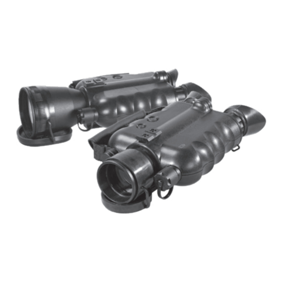
Page 11: Description And Data
FIGuRE 1-1. VOyaGER 3 aND VOyaGER 5 NIGHT VISION bI-OculaRS b. Features the voyager has the following important features: •... - Page 12 Principle of Operation the atn voyager is a hand-held night vision system that enables walking, short-range surveillance and administering first aid in both moonlight and starlight. the device can be also equipped with an infrared light-emitting source. Bi-ocular utilizes the principle of intensification of the residual light which is reflected from the surrounding objects.
- Page 13 F. automatic Highlight Protective System The Automatic Highlight Protective System analyzes light exposure with the sensor. If the level of light exposure exceeds allowable the green indicator will light on in the Fov. If high light exposure is kept more than 10 seconds the IIt will automatically turn off. If the unit will move from the bright/excessive light the IIt will turn on again.
- Page 14 TablE 1-1. SPEcIFIcaTION Voyager 3x Voyager 5x MEcHaNIcal DaTa: Dimensions 8.7”x5.5”x3.1” / 10”x5.5”x3.4”/ (Length x Width x Height) 220x140x78 mm 254x140x86 mm Weight 2.3 lb/1 kg 2.9 lb/1.3 kg ElEcTRIcal DaTa: Battery one aa (1.5 v) or Cr123a (3 v) Cell life at 20 ˚C: aa alkaline Battery 30 hours...
- Page 15 on/oFF BUtton proXImIty SenSor BUtton eye CUpS SeNSoR of HIGHLIGHT proteCtIve SyStem WITH CAP top raIl BATTeRy HoUSING CAP oBjeCtIve lenS FoCUS LeNS CAP WITH IR fILTeR proXImIty SenSor HAND STRAP DIopter aDjUStment rInGS NeCK STRAP’S BUCKLeS BoTToM RAIL WITH TRIPoD SoCKeT FIGuRE 1-2.
-
Page 16: Voyager Standard Components
Figure 1-3 and presented in table 1-2. FIGuRE 1-3. VOyaGER STaNDaRD cOMPONENTS TablE 1-2. VOyaGER STaNDaRD cOMPONENTS ITEM DEScRIPTION atn voyager Bi-ocular objective lens Cap eye Cups Cap of Highlight Protective System Sensor Hand Strap Battery adapter... -
Page 17: Standard Components
6) battery adapter allows the atn voyager to accept the Cr123a lithium and aa size batteries to power the unit. Installed in the battery cap in Cr123a usage position. - Page 18 8) IR450 Infra-Red Illuminator Kit powerful 450mW detachable infra-red illuminator is an ef- ficient tool for long range nighttime observation in the total darkness. 9) Neck Strap 10) Operating Manual provides equipment description, use of operator controls and preventative maintenance checks and service. 11) Soft case a protective case used to store voyager and accessories.
-
Page 19: Section Ii. Operating Instructions
SEcTION II OPERaTING INSTRucTIONS... -
Page 20: Installation Procedures
2.1. INSTallaTION PROcEDuRES 2.1.1. baTTERy INSTallaTION a. Install cR123a battery as follows: With the battery adapter screwed in the battery housing cap as shown on Figure 2-1 you can use one Cr123a type battery. put the Cr123a battery observing the polarity indications on the battery compartment surface. -
Page 21: Neck Strap Installation
2.1.2. NEcK STRaP INSTallaTION pass the end of the strap through the bi-ocular’s strap mount eyelet from the bottom. then pass it through the strap’s buckle as shown in the Figure 2-3. pull the strap to take up any slack and make sure the strap will not loosen from the buckle. -
Page 22: Ir450 Installation
2.1.4. IR-450 INSTallaTION Ir-450 detachable infrared illuminator can be mounted on the top or bottom rail of bi-ocular. 1. loosen the Ir-450 fixing screw. 2. mount the Ir-450 on the rail of voyager and tighten the fixing screw. FIXInG SCreW FIGuRE 2-5. -
Page 23: Operating Procedures
2.2. OPERaTING PROcEDuRES 2.2.1. cONTROlS aND INDIcaTORS the voyager is designed to adjust for different users and corrects for most differences. the controls of the bi-ocular are shown on Figure 2-6. the functions of controls and indicators are described in the table 2-2. DIopter aDjUStment on/oFF BUtton rInGS... -
Page 24: Preparation For Operation
cONTROlS FuNcTION Sensor of Highlight The automatic Highlight Protective System ana- protective System lyzes light exposure with the sensor. Identifies the user’s intention to look through the proximity Sensor bi-ocular by turning the unit automatically on. When proximity sensor is on, the indicator in the Fov will lights red. -
Page 25: Focusing
etc. can damage the Voyager. avoid exposing the Voyager to these types light sources. to start the operations in dark conditions: 1. make visual estimation if the illumination level in the viewing area is less than 1 lux (late twilight sky conditions). 2. -
Page 26: Ir Illuminator Operation
Staying in the dark, switch on your night vision device. If the visibility is low, you may use atn Ir450 to improve the situation. Still, you should remember that the Ir illuminator is just a source of infrared light so the greater is the chosen range of observation, the lesser its brightness becomes. - Page 27 Ir450 Infrared Illuminator can be mounted with voyager onto the picatinny rail. the atn Ir450 is powered with one Cr123a lithium battery. to install the battery unscrew the cap of the battery housing and in- sert the battery following the polarity arrows marked on the hous- ing.
-
Page 28: Shut-Down Operation
2.2.8. SHuT-DOwN OPERaTIONS 1. push on/oFF button to turn the bi-ocular off. the green of the image intensifier tube glow will fade to black. 2. replace the protective cap on the front lens. -
Page 29: Section Iii. Operational Defects
SEcTION III OPERaTIONal DEFEcTS... -
Page 30: Zeroing Operational Defects
Shading always begins on the edge and migrates in- ward eventually across the entire image area. Shading is a high contrast area with a distinct line of demarcation. Contact atn or point of purchase for warranty/repair procedures. SHADING FIGuRE 3-1. -
Page 31: Edge Glow
However, some types of blemishes can get worse over time and interfere with the usabil- ity of the device. If you believe a blemish is a cause for rejection, warranty or repair please atn or point of purchase for warranty/ repair procedures. - Page 32 (Figure 3-3). not all bright spots make the atn voyager rejectable. Cup your hand over the lenses to block out all light. If the bright spot re- mains, return the atn voyager.
- Page 33 c. black Spots. these are cosmetic blemishes in the image intensifiers or dirt or debris between the lenses. Black spots are acceptable as long as they do not interfere with viewing the image. No action is re- quired if this condition is present unless the spots interfere with the usability of the device.
- Page 34 E. chicken wire. an irregular pattern of dark thin lines in the field of view either throughout the image area or in parts of the image area (Figure 3-5). Under the worst-case condition, these lines will form hex- agonal or square-wave shaped lines. this is typically viewed in high light conditions.
-
Page 35: Section Iv. Maintenance Instructions
SEcTION IV MaINTENaNcE INSTRucTIONS... -
Page 36: Preventive Maintenance Checks And Services (Pmcs)
4.1. PREVENTIVE MaINTENaNcE cHEcKS aND SERVIcES (PMcS) 4.1.1. PuRPOSE OF PMcS pmCS is performed daily when in use to be sure that the voyager is ready at all times. procedures listed in table 4-1 are a systematic inspection of the voyager that will enable you to discover defects that might cause the device to fail on a mission. - Page 37 lOcaTION ITEM NOT FuNcTION- SEq. TO cHEcK/ PROcEDuRE ING aT OPTIMal SERVIcE lEVEl IF Check to make sure battery adapter is miss- Battery adapter is present. remove ing, contacts adapter / battery adapter and inspect damaged or Compartment for corrosion, moisture, cor- corroded.
- Page 38 lOcaTION ITEM NOT FuNcTION- SEq. TO cHEcK/ PROcEDuRE ING aT OPTIMal SERVIcE lEVEl IF Inspect for dirt, dust, or cor- mounting rail rosion. If necessary, clean socket with water. remove all items and shake out loose dirt or foreign mate- Carrying Case rial.
-
Page 39: Troubleshooting Procedures
If the equipment malfunction is not listed or actions listed do not correct the fault, notify atn or your point of purchase. - Page 40 SEq. MalFuNcTION TEST OR INSPEcTION cORREcTIVE acTION Diopter adjust- Check to see if the If damaged, refer ment cannot diopter adjustment rings to higher level of be made are bent or broken maintenance. Battery adapt- Check for damaged bat- If damaged, refer er difficult to tery adapter.
-
Page 41: Maintenance Procedures
4.3. MaINTENaNcE PROcEDuRES 4.3.1. bI-OculaR MaINTENaNcE the voyager maintenance consists of external inspection of its components for serviceability, cleaning and installation of the standard and optional accessories. maintenance instructions covered elsewhere in this manual (pmCS, troubleshooting, etc.) are not repeated in this section. cauTION The Voyager is a precision electron-optical instrument and must be handled carefully at all times to prevent damage. - Page 42 3. Clean the bi-ocular and accessories. 4. replace all items in the case.
- Page 43 aPPENDIx a (Reference) ESTIMaTION OF aMbIENT IlluMINaTION lEVEl TablE a-1. STaNDaRD NaTuRal lIGHT cONDITIONS aND IlluMINaTION ValuES STaNDaRD NaTuRal lIGHT IlluMINaTION ValuE, cONDITIONS Quarter moon 0.05 Full moon 0.30 late twilight sky 1.00 twilight sky 10.00 overcast sky in the daytime 500.00...
- Page 44 Spare parts list. the amount and assortment of the spare parts needed should be arranged with each contract individually. TablE b-1. aTN VOyaGER 3/5 SPaRE PaRTS lIST PaRT NO. DEScRIPTION FIG.
- Page 45 FIGuRE b-1. NIGHT VISION bI-OculaR aND accESSORIES 4-11...
- Page 46 4-12...
-
Page 47: For Technical Information
FOR TEcHNIcal INFORMaTION aTN cORP. 1341 San mateo avenue South San Francisco, Ca 94080 (800) 910-2862 (650) 989-5100 tel. (650) 875-0129 fax www.atncorp.com info@atncorp.com InFo-1... - Page 48 800-910-2862, 650-989-5100; fax: 650-875-0129 European Office the following countries can use our toll free number: 00 800 9102-8620 Austria, france, Germany, Holland, Italy, Spain, Sweden, Switzerland For other countries, please use 38 048-7770214 or 38 048-7770345 www.atncorp.com ©2010 atn Corporation...
Need help?
Do you have a question about the VOYAGER 3 and is the answer not in the manual?
Questions and answers