Table of Contents
Advertisement
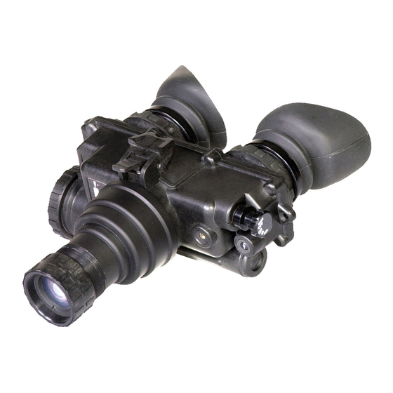
ATN PVS-7
NIGHT VISION GOGGLES
operator'S ManUal (pVS-7) reVISIon 3 - aprIl 2009
o p e r a t o r ' s m a n u a l
Impor tant Expor t Restrictions ! Commodities,
products, technologies and services contained in
this manual are subject to one or more of the export
control laws and regulations of the U.S. Government
and they fall under the control jurisdiction of either the
US Department of State or the US BIS-Department
of Commerce. It is unlawful and strictly prohibited
to export, or attempt to export or otherwise transfer
or sell any hardware or technical data or furnish any
service to any foreign person, whether abroad or
in the United States, for which a license or written
approval of the U.S. Government is required, without
first obtaining the required license or written approval
from the Department of the U.S. Government having
jurisdiction. Diversion contrary to U.S. law is prohibited.
Advertisement
Table of Contents

Related Manuals for ATN PVS-7


Summary of Contents for ATN PVS-7
-
Page 1: Night Vision Goggles
ATN PVS-7 NIGHT VISION GOGGLES operator’S ManUal (pVS-7) reVISIon 3 - aprIl 2009 o p e r a t o r ’ s m a n u a l Impor tant Expor t Restrictions ! Commodities, products, technologies and services contained in this manual are subject to one or more of the export control laws and regulations of the U.S. - Page 2 Corp. atn Corp. assumes no responsibility or liability for any errors or inaccuracies that may appear in this book.
-
Page 3: Safety Summary
SAFETY SUMMARY CAUTIONS • The ATN PVS-7 is a precision optical instrument and should be handled carefully to prevent its damage. • Do not scratch the external lens surfaces or touch them with your fingers. • To protect the image intensifier, keep the lens cap on the objec- tive lens on when the device is not in use or when it is checked out in daylight conditions. - Page 4 NOTES • Do not test the device in daylight conditions even with the day- light filter/lens cap on for more than ten (10) minutes. • To protect the device from damage do not direct it to the bright light sources (a fire, headlights of the automobile, lanterns, etc.). •...
- Page 5 EqUIPMENT LIMITATIONS to avoid physical and equipment damage when using the atn pVS-7, carefully read and understand the following equip- ment limitations. • The equipment requires some night light (moonlight, starlight, etc.) to operate. the level of equipment performance depends upon the level of light.
-
Page 6: Table Of Contents
TABLE OF CONTENTS SAFETY SUMMARY CHAPTER 1: Introduction Section I: General Information 1-1 Scope 1-2 reporting equipment Improvement recommendations (eIr) 1-3 Glossary 1-4 administrative Stowage Section II: equipment Description 1-5 equipment Characteristics, Capabilities and Features 1-6 equipment Capabilities 1-7 Specifications Section III: operation principles 1-11 1-8 Mechanical Functions... - Page 7 CHAPTER 3: Maintenance Instructions Section I: troubleshooting procedures 3-1 troubleshooting Section II: Maintenance procedures 3-2 Cleaning the pVS-7 3-3 Head Mount Maintenance APPENDIX A: System Optional Equipment FOR TECHNICAL INFORMATION InFo-1...
-
Page 9: Chapter 1: Introduction
CHAPTER 1 INTRODUCTION... -
Page 10: Section I: General Information
BrIGHt SpotS. these can be defects in the image area pro- duced by the pVS-7 . this condition is caused by a flaw in the film on the micro-channel plate. a bright spot is a small, non-uniform, bright area that may flicker or appear constant. - Page 11 FlaSHInG. this is a defect in the image area of the pVS-7 . the image appears to flicker or flash.
-
Page 12: Administrative Stowage
Chapter 3 of this manual. this will ensure the pVS-7 remains in a mission ready-condition during storage. 1-5 wARRANTY INFORMATION... -
Page 13: Section Ii: Equipment Description
SECTION II: EqUIPMENT DESCRIPTION 1-5 EqUIPMENT CHARACTERISTICS, CAPABILITIES AND FEATURES the pVS-7 includes the items shown in Figure 1-1. See table 1-1 and Figure 1-1 for Standard and optional equipment. A. Goggle Assembly. the goggle assembly consists of four pri- mary sub-assemblies;... - Page 14 Figure 1-1. PVS-7 Components...
- Page 15 Shoulder Strap assembly atn3144267 light Interference Filter atn5009737 Sacrificial Window atn3144264 Ir Spot/Flood lens atn3187441 Ba-5567/U lithium battery Demist Shield assembly atn31442632 pVS-7 assembly atn-pVS7-001 aa alkaline Batteries Carrying Case atn3187392 Helmet Mount assembly atn3256390 neck Cord atn3260933 Shipping/Storage Case atn3187393...
-
Page 16: Equipment Capabilities
Interference Filter (lIF), compass, helmet mount assembly and an Ir spot/flood lens (see Figure 1-1). also included is a shipping and storage case. the pVS-7 may be supplied in hard shipping and storage case. Batteries may also be stored in the shipping and storage case. - Page 17 Table 1-4. Mechanical Data IteM lIMItS Shipping and Storage Case Size: Approx. 17 ”x12”x7 ” Weight: 6.7 lbs. Soft Carrying Case Size: Approx. 14”x8” Goggle (See note) Weight 1.5 lbs NOTE The weight of the PVS-7 does not include accessories.
- Page 18 Table 1-5. Optical Data IteM lIMItS Magnification 1.0X Field of View 40° eyepiece Focus +2 to -6 diopters Focus range 25 cm (9.8”) to infinity Table 1-6. Environmental Data IteM lIMItS operating temperature -40°C to +50°C Storage temperature -50°C to +70°C Illumination required overcast starlight to moon- light...
-
Page 19: Section Iii: Operation Principles
SECTION III: OPERATION PRINCIPLES 1-8 MECHANICAL FUNCTIONS Mechanical adjustments of the pVS-7 allow for physical differences between individual operators using the system. the goggle’s func- tions include the power switch, interpupillary adjustment, release latch, eye relief adjustment, diopter adjustment, Ir spot/flood focus (optional), compass illumination (optional), and objective lens fo- cus. -
Page 20: Optical And Electrical Functions
1-9 OPTICAL AND ELECTRICAL FUNCTIONS the optical functions include an objective lens, image intensifier, a collimator lens and two eyepieces. the objective lens collects light reflected from the night scene by the moon, stars or night sky and inverts the image and focuses that image on the image intensifier. the electrical functions include the following. -
Page 21: Consumable Items
goggle. to turn the goggle back on, turn the switch to reSet/oFF position and then to on again. 1-10 CONSUMABLE ITEMS Items listed in the table 1-7 are recommended for operator main- tenance. Table 1-7. Consumable Items IteM lIMItS lens paper Color Swabs alcohol 1-13... - Page 22 1-14...
-
Page 23: Chapter 2: Operating Instructions
CHAPTER 2 OPERATING INSTRUCTIONS... -
Page 24: Section I: Operating Procedures
AND MUST BE HANDLED CAREFULLY AT ALL TIMES. 2-2 CONTROLS AND INDICATORS the pVS-7 is designed to adjust for different users and corrects for most differences in eyesight. the controls and indicators for the pVS-7 are shown or described in Figure 2-1 and tables 2-1 and 2-2. - Page 25 Ir. Illuminates leD indicator in left eyepiece. NOTE Some PVS-7’s contain an additional momentary IR function. For momentary IR, continue to turn the switch knob clockwise, past ON and without pulling. The switch will return to the ON position when released.
- Page 26 IteMS ControlS anD FUnCtIonS InDICatorS objective Focus Focuses objective lens. adjusts for sharpest image of viewed object. Battery polarity In- the feature, molded into the pVS- dicator 7, shows the proper orientation of the batteries. latch latch used for separation of gog- gle assembly from head mount/ helmet mount assembly.
-
Page 27: Section Ii: Preventive Maintenance Checks And Services (Pmcs)
NANCE CHECKS AND SERVICES (PMCS) 2-3 PURPOSE OF PMCS pMCS is performed daily when the pVS-7 is in use to ensure that the sight is ready at all times. procedures are a systematic inspec- tion of the goggle that will enable you to discover defects that might cause the pVS-7 to fail on a mission. - Page 28 InterVal & SeQUenCe IteM to Be InSpeCteD/ proCeDUre CarrYInG CaSe - Check for dirt, moisture and mildew. Clean with mild detergent and wa- ter. Dry with lint-free cloth. BatterIeS - remove batteries. Check for corrosion on terminals and dirt or moisture in battery cap.
- Page 29 InterVal & SeQUenCe IteM to Be InSpeCteD/ proCeDUre reSet/oFF-on-Ir/pUll SWItCH - remove any batteries and turn the switch from reSet/ oFF to on or Ir/pUll. each position should have a definite stopping point. Inspect for bro- ken or missing knob. HEAD MOUNT StrapS anD paDS - Check for cuts tears, fraying, holes, cracks or defective fasteners.
- Page 30 InterVal & SeQUenCe IteM to Be InSpeCteD/ proCeDUre tIlt aDJUStMent - Verify knob locks tilt in place and full range of tilt is available with knob loosened. SoFt CarrYInG CaSe - remove all items and shake out loose dirt or foreign material. In- spect for tears, cuts, excess wear or damage to mounting clips.
- Page 31 InterVal & SeQUenCe IteM to Be InSpeCteD/ proCeDUre CoMpaSS aSSeMBlY - Inspect for dirt, dust scratches or damage. If necessary, clean with water and dry with lens paper. Install compass assembly and turn on goggle. When the illumination button is depressed, the compass should be visible.
-
Page 32: Section Iii: Assembly And Preparation
2. Check contents of shipping and storage case for completeness. (see Figure 1-1.) 3. remove the carrying case from the shipping and storage case. open carrying case (Figure 1-1), remove the pVS-7 and check con- tents for completeness. 4. Inspect the goggle for obvious evidence of damage to optical surfaces, body, eyecups. - Page 33 WITH EXTREME CARE BECAUSE OF HEAT. IF YOU INHALE SULFUR DIOXIDE, SEEK MEDICAL ATTENTION. the pVS-7 will operate with either of the two battery types identified in table 2-3. Batteries are not supplied with the pVS-7 and must be obtained. Table 2-3. Estimated Battery Life...
- Page 34 C. Installation of the Eyecups. perform the following procedure to install the eyecups onto the pVS-7. refer to Figure 2-2. 1. Carefully press each eyecup over the diopter cell retainer. 2. rotate each eyecup into proper viewing position. adjust for best eye fit.
- Page 35 Demist Shields Compass IR Spot/Flood Lens Sacrificial window Figure 2-3. Installation of Demist Shields, Sacrificial window D. Installation of the Demist Shields. perform the following pro- cedure to install the demist shields on the diopter lenses. refer to Figure 2-3. CAUTION IF THE DEMISTING SHIELDS NEED TO BE CLEANED, MAKE SURE THE SHIELDS ARE DRY AND USE DRY LENS PAPER.
- Page 36 F. Installation of the Compass Assembly. Figure 2-4. Installation of Compass NOTE a. Prepare the PVS-7 for operation (paragraph 2-6). b. Leave LIF in place when installing the compass assembly. c. Ensure the Neck cord is secured to the compass and clothing before installing.
- Page 37 (with compass illumina- tion button pointing down). See Figure 2-3. 5. ensure that the compass fits tightly to the pVS-7. NOTE The o-ring must be in place in the compass assembly in order for the compass to fit properly.
- Page 38 Figure 2-6. Installation of the IR Spot/Flood Lens I. Installation and Adjustment of the Head Mount Assembly. perform the following procedures for donning the head mount. NOTE Do not don the head mount while the PVS-7 is attached to it. 2-16...
- Page 39 Sliding Bar Chin Cup Buckles Figure 2-7. PVS-7 Head Mount Adjustments 1. prior to donning the head mount, loosen the four chin straps so the ends of each strap arc approximately two inches from the slid- ing bar buckles (See Figure 2-7) 2.
- Page 40 7. adjust chin strap and vertical adjustment until the chin cup and headband assembly arc in comfortable but firm position. NOTE After installing the PVS-7, minor strap adjustments may be neces- sary to achieve comfort. 8. refer to paragraph 2-7, a for operating procedures of head mount assembly.
- Page 41 M. Installation of the Helmet Mount Assembly (Optional) to the PASGT Helmet. 1. remove mount assembly from the carrying case. refer to Figure 2-8 for the helmet mount features. Catch Helmet Buckle Strap Lever Tilt Adjustment Side Rear Socket Front Bracket Button Bracket Figure 2-8.
-
Page 42: Installation Of The Quick Disconnect Helmet Mount Assembly
Nape Strap Fastener Tabs Chin Strap Nape Straps Loop the nape strap fastener tabs around the corners of the chin strap and snap closed. After closure, the snaps will be on the outside, away from your chin. Figure 2-9. Nape Strap Installation 7. - Page 43 2. If the mount assembly and clip/strap assembly are connected, remove the mount assembly. to do this, push the release lever at the top center of the mount and slide the two assemblies apart. 3. adjust the clip/strap assembly to fit the helmet size being used. 4.
-
Page 44: Operating Procedures
3. align the pVS-7 ‘s latch (Figure 2-1) to the head mount socket (See Figure 2-8). press and hold down the latch lever while install- ing the goggle into the head mount socket. - Page 45 10. adjust the eye relief distance by pressing the socket release button (See Figure 2-1) and sliding the pVS-7 fore or aft to obtain a full field of view of the image. readjust the diopter rings for best image.
- Page 46 K. adjust the eye relief distance by pressing the socket release but- ton (see Figures 2-1) and sliding the pVS-7 fore or aft to obtain a full field of view of the image. readjust the diopter rings for the best image.
- Page 47 (Figure 2-11). Figure 2-11. Flip-up Helmet Mount NOTE The PVS-7 will be turned off automatically when flipped up. The PVS-7 will not turn on automatically when flipped down. 11. to flip down, grasp the goggle housing and rotate down and forward until the latch is firmly engaged.
- Page 48 These adjustments oper- ate independently and must be made separately. 4. Hold the pVS-7 with your left hand and fold the left eyecup over the eyepiece with your left thumb or forefinger to obstruct view through the left eyepiece.
- Page 49 4. the compass readings should change when you move your head from side to side. rotate or tap compass slightly to ensure compass is operating correctly. Hold the pVS-7 in a level position to assure live rotation of the compass scale.
- Page 50 CAN BE DETECTED BY THE ENEMY USING NIGHT VISION DEVICES. 1. pull the reSet/oFF-on-Ir/pUll switch knob (Figure 2-1) out and rotate clockwise to the Ir position. With the pVS-7 held to the eyes, observe that a red light appears in the left eyepiece. this in- 2-28...
-
Page 51: Preparation For Stowage
2. to operate with the Ir Spot/Flood lens: pull the reSet/oFF- on-Ir/pUll switch knob out and rotate clock-wise to the Ir posi- tion. With the pVS-7 held to the eyes, turn the Ir spot/flood until you have achieved the optimum illumination of the desired distance. - Page 52 8. return to storage area. Figure 2 - 14. PVS-7 Shipping/storage case 2-30...
-
Page 53: Chapter 3: Maintenance Instructions
CHAPTER 3 MAINTENANCE INSTRUCTIONS... -
Page 54: Section I: Troubleshooting Procedures
C h e c k for d efe c - replace battery(ies) or tive, missing or im- install correctly properly installed battery(ies) If pVS-7 still fails to acti- vate, refer to higher level of maintenance 2. Ir indicator Visual refer to higher level of... - Page 55 8. pVS-7 does Visual return both the pVS-7 n o t s h u t o f f and head mount to higher when removed level of maintenance f r o m...
- Page 56 Check socket or If damaged; return both goggle do not latch for damage head mount or helmet catch mount and pVS-7 to higher level of mainte- nance 11. Helmet Visual If damaged, refer to mount will higher level of mainte-...
- Page 57 MalFUnCtIon teSt / InSpeCtIon CorreCtIVe aCtIon 16 C o m p a s s Visual Make sure the pVS-7 is display is not focused for infinity. If so clear and compass display is still not clear refer to high- er level of maintenance 17.
-
Page 58: Section Ii: Maintenance Procedures
CAUTION FOR PROTECTION OF THE IMAGE INTENSIFIER, DISCONNECT THE PVS-7 FROM THE HEAD MOUNT PRIOR TO REPLACING BROW PADS. 1. Firmly grasp the head mount and remove the old brow pad. 2. Gently press on the new brow pad. lightly smooth out any wrin- kles in the new brow pad. - Page 59 Lower Strap Retention Tab Lower Strap Retention Tab Lower Strap Retention Tab Figure 3-1. Re-installing the Neck Pad 3. repeat steps 1 and 2 for the other side of the headband and neck pad if necessary. C. Lacing the Sliding Bar Buckles. While donning and adjust- ing the head mount, it is possible for a strap to slip out of a slide fastener.
-
Page 60: Appendix A: System Optional Equipment
APPENDIX A SYSTEM OPTIONAL EqUIPMENT Table A-1. System Optional Equipment IteM DeSCrIptIon QUant part no Helmet Mount assy. atn3256390 objective Filter assy., lIF atn5009737 Sacrificial Window assy. atn3144264 Demist Shield assy. atn31442632 Case, Shipping/Storage atn3187393 Battery, lithium B-5567/U 3X a local lens assy. atn5009717 Kit adapter, 3X afocal, 7D atn5009718... -
Page 61: For Technical Information
FOR TECHNICAL INFORMATION ATN CORP. 1341 San Mateo avenue South San Francisco, Ca 94080 (800) 910-2862 (650) 989-5100 tel. (650) 875-0129 fax www.atncorp.com info@atncorp.com InFo-1... - Page 62 FOR NOTE InFo-2...
- Page 63 InFo-3...
- Page 64 800-910-2862, 650-989-5100; fax: 650-875-0129 European Office the following countries can use our toll free number: 00 800 9102-8620 austria, France, Germany, Holland, Italy, Spain, Sweden, Switzerland For other countries, please use 38 048-7770214 or 38 048-7770345 www.atncorp.com ©2008 atn Corporation...
Need help?
Do you have a question about the PVS-7 and is the answer not in the manual?
Questions and answers