Table of Contents
Advertisement
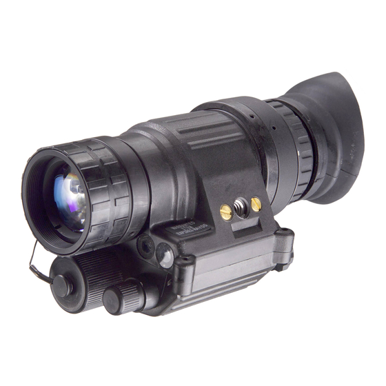
ATN PVS-14
ATN 6015
NIGHT VISION MULTI-PURPOSE SYSTEMS
operator'S ManUal (pVS-14/6015) reVISIon 2 - aprIl 2011
o p e r a t o r ' s m a n u a l
Important Export Restrictions! Commodities, products,
technologies and services contained in this manual are
subject to one or more of the export control laws and
regulations of the U.S. Government and they fall under the
control jurisdiction of either the US Department of State
or the US BIS-Department of Commerce. It is unlawful
and strictly prohibited to export, or attempt to export or
otherwise transfer or sell any hardware or technical data or
furnish any service to any foreign person, whether abroad
or in the United States, for which a license or written
approval of the U.S. Government is required, without
first obtaining the required license or written approval
from the Department of the U.S. Government having
jurisdiction. Diversion contrary to U.S. law is prohibited.
Advertisement
Table of Contents

Subscribe to Our Youtube Channel
Related Manuals for ATN ATN PVS-14


Summary of Contents for ATN ATN PVS-14
- Page 1 ATN PVS-14 ATN 6015 NIGHT VISION MULTI-PURPOSE SYSTEMS operator’S ManUal (pVS-14/6015) reVISIon 2 - aprIl 2011 o p e r a t o r ’ s m a n u a l Important Export Restrictions! Commodities, products, technologies and services contained in this manual are subject to one or more of the export control laws and regulations of the U.S.
- Page 2 Corp. atn Corp. assumes no responsibility or liability for any errors or inaccuracies that may appear in this book.
-
Page 3: Safety Summary
SAFETY SUMMARY CAUTIONS • The ATN PVS-14 and ATN 6015 are precision optical instruments and must be handled carefully at all times to prevent damage. • Do not scratch the external lens surfaces or touch them with your fingers. • Wiping demisting shield with lens paper while wet or with wet lens paper can damage the coating. - Page 4 WARNING Toxic Material the image intensifier’s phosphor screen contains toxic materials. • If an image intensifier breaks, be extremely careful to avoid inhaling the phosphor screen material. Do not allow the mate- rial to come in contact with the mouth or open wounds on the skin.
- Page 5 • The purpose of the illuminator is to view at close distance up to 3 meters when additional illumination is needed. CAUTION • The ATN PVS-14 and ATN 6015 are a precision optical instru- ment and must be handled carefully at all times to prevent damage.
-
Page 6: Table Of Contents
TABLE OF CONTENTS SAFETY SUMMARY CHAPTER 1. INTRODUCTION 1.1. General Information 1.1.1. Scope 1.1.2. Warranty Information 1.1.3. technical Information 1.1.4. nomenclature Cross-reference list 1.1.5. list of abbreviations and acronyms 1.1.6. Glossary 1.2. Equipment Description 1.2.1. equipment Characteristics, Capabilities, and Features 1.2.2. - Page 7 2.3.2. Installation of Battery 2-21 2.3.3. Installation of eyecup or eyeguard 2-23 2.3.4. Installation of Demist Shield 2-23 2.3.5. Installation of Sacrificial Window 2-24 2.3.6. Installation of lIF 2-24 2.3.7. Installation and adjustment of Headmount 2-25 2.3.8. Installation of Headmount/Helmet Mount adapter 2-27 2.3.9.
-
Page 8: How To Use This Manual
3.3.2. Headmount Maintenance 3.3.3. neck Cord Maintenance Appendix A. Components of End Item (COEI) and Basic Issue Items (BII) Lists Appendix B. Additional Authorization List (AAL) Appendix C. Expendable and Durable Items List Subject Index IND-1 HOW TO USE THIS MANUAL •... -
Page 9: Chapter 1. Introduction
CHAPTER 1 INTRODUCTION... -
Page 10: General Information
Multi-Use night Vision Monocular (MUnVM) atn pVS-14 and atn 6015 hereinafter referred to as the MUnVM. the MUnVM is a self-contained night vision device that enables improved night vision using ambient light from the night sky (moon, stars, skyglow, etc.). - Page 11 TABLE 1.1. NOMENCLATURE CROSS-REFERENCE LIST COMMON NAME OFFICIAL NOMENCLATURE Battery Battery nonrechargeable Battery Cap Cover Battery retainer Carrying Case Case, Infrared equipment Carrying Case Strap Strapping Compass Compass assembly Demist Shield lens, Infrared receiver eyeguard eyeguard, optical eyepiece lens Cap Cap, protective, Dust Headmount Headset assembly...
-
Page 12: List Of Abbreviations And Acronyms
1.1.5. LIST OF ABBREVIATIONS AND ACRONYMS additional authorization list Basic Issue Items CaGeC Commercial and Government entity Code Centimeters CoeI Components of end Item Corrosion prevention and Control- Common table of allowances- Department of the army end Item Code equipment Improvement recommendation Field Manual Hours Infrared... -
Page 13: Glossary
Standard Form table of Distribution and allowances- technical Manual table of organization and equipment- Unit of Measure Volts, direct current 1.1.6. GLOSSARY BlaCK SpotS. these are cosmetic blemishes in the image inten- sifier of the MUnVM or dirt or debris between the lenses. BrIGHt SpotS. - Page 14 EDGE GLOW. This is a defect in the image area of the monocular. edge glow is a bright area (sometimes sparkling) in the outer por- tion of the viewing area. eMISSIon poInt. a steady or fluctuating pinpoint of bright light in the image area and does not go away when all light is blocked from the objective lens of the monocular.
- Page 15 note. essential information of special importance, interest, or aid in job performance. pHotoCatHoDe. the input optic of an image intensifier that ab- sorbs light energy and in turn releases electrical energy in the form of an electron image. SCIntIllatIon. a faint, random, sparkling effect throughout the image area.
-
Page 16: Equipment Description
1.2 EQUIPMENT DESCRIPTION 1.2.1. EQUIPMENT CHARACTERISTICS, CAPABILITIES, AND FEATURES the MUnVM is a hand-held, headmounted, helmet mounted, or weapon mounted night vision system that enables walking, weapon firing, short-range surveillance, map reading, vehicle maintenance, and administering first aid in both moonlight and starlight. each unit allows for vertical adjustment (by using head strap), fore-and-aft adjustment, objective lens focus and eyepiece focus. - Page 17 tetHerInG CorD HeaD/HelMet HeaDMoUnt MoUnt aDapter tHIn BROWPAD WEAPON MOUNT HelMet MoUnt MeDIUM anD THICK BROW- paDS CarrYInG CaSe BatterY CartrIDGe operator’S ManUal lenS paper DeMISt neCK CorD SHIelD BatterY SaCrIFICIal WINDOW eYeGUarD CarrYInG oBJeCtIVe CaSe Strap lenS Cap LIF W/ ContaIner WRENCH MonoCUlar...
- Page 18 CoMpaSS 3X MaGnIFIer (aDDItIonal IteM) FIGURE 1.2. 3X MAGNIFIER AND COMPASS FOR PVS-14/6015 1-10...
- Page 19 (See FIGUre 1.1. For DetaIlS) SHIppInG StoraGe CaSe FIGURE 1.3. SHIPPING AND STORAGE CASES FOR PVS-14/6015 1-11...
- Page 20 eYepIeCe lenS oBJeCtIVe lenS POWER SWITCH GaIn BatterY Control FIGURE 1.4. MULTI-USE NIGHT VISION MONOCULAR tethering Cord – the tethering cord (Figure 1.1.) enables the user to attach the compass or 3X magnifier to a button hole or belt loop to guard against dropping orlosing these items. 3X Magnifier –...
-
Page 21: Equipment Data
d. Headmount/Helmet Mount Adapter this item (Figure 1.1.) is attached to the monocular to allow its use with the headmount or helmet mount. It allows mounting in front of the left or right eye. e. Weapon Mount the weapon mount (Figure 1.1.) adapts the monocular to the re- ceiver rail as configured for the modular weapon system kit. - Page 22 TABLE 1.4. MECHANICAL DATA ITEM CHARACTERISTICS Size: Approx.14” X 9.5” X 8” Shipping and Storage Case Weight: 2.4 lbs. Carrying Case Size: Approx. 14” X 8” Monocular (see note) Weight: 14 ounce NOTE Weight of the monocular does not include accessories. TABLE 1.5.
-
Page 23: Principles Of Operation
1.3. PRINCIPLES OF OPERATION 1.3.1. MECHANICAL FUNCTIONS the mechanical functions of the nVMpS allow for differences in the physical features of individual operators and provide for operating the system. these functions include the power switch, eye relief adjustment, diopter adjustment, gain control, and objective focus. the mechanical controls are identified in Figure 1.5. -
Page 24: Optical Functions
1.3.2 OPTICAL FUNCTIONS the optical functions include an objective lens, image intensifier and eyepiece lens (Figure 1.6). the objective lens collects light re- flected from the night scene by the moon, stars, or night sky, inverts the image and focuses that image on the image intensifier. the im- age intensifier converts the captured light into a visible image and reinverts the image which can then be viewed through the eyepiece lens. -
Page 25: Chapter 2. Operating Instructions
CHAPTER 2 OPERATING INSTRUCTIONS... -
Page 26: Description And Use Of Operator's Controls And Indicators
2.1. DESCRIPTION AND USE OF OPERATOR’S CONTROLS AND INDICATORS NOTE The MUNVM is a precision electro-optical instrument, so handle it carefully. If the equipment fails to operate, refer to the Troubleshooting Procedures in Chapter 3. 2.1.1. OPERATOR CONTROLS AND INDICATORS the MUnVM is designed to adjust for different users and cor- rects for most differences in eyesight. - Page 27 TABLE 2.1. MONOCULAR CONTROLS AND INDICATORS CONTROLS AND FUNCTIONS INDICATORS power Switch Controls monocular and Ir source, on or oFF. reSet/ Same as system oFF. also resets monocular after high light cut-off. Monocular activated. turn the knob clockwise to momentarily ac- tivate the Ir source.
-
Page 28: Preventive Maintenance Checks And Services (Pmcs)
2.2. PREVENTIVE MAINTENANCE CHECkS AND SERVICES (PMCS) 2.2.1. PREVENTIVE MAINTENANCE CHECkS AND SERVICES TABLE a. General to ensure the readiness of the MUnVM, perform the preventive maintenance procedures in accordance with table 2.2., prior to each mission. preventive maintenance procedures include inspec- tion, cleaning, and performance of the checkout procedures. - Page 29 to know if the equipment is ready or available for its intended mis- sion or operation. You must do the procedure at the time stated in the interval column. (5) Not Fully Mission Capable If: Column. Information in this column tells you what faults will keep your equipment from being capable of performing its primary mission.
- Page 34 2-10...
- Page 35 2-11...
- Page 36 2-12...
- Page 37 2-13...
-
Page 38: Resolution Check Using The Ts-4348/Uv Test Set
2.2.2. RESOLUTION CHECk USING THE TS-4348/UV TEST SET NOTE The TS-4348/UV Test Set can be used by the operator to check the resolution of a monocular at any time. NOTE The TS-4348/UV Test Set can be used by Direct Support/Inter- mediate Level to perform the resolution testing 180 Day Serv- ice. - Page 39 (2) Install the lIF per paragraph 2.3.6. (3) turn off the room light and let your eyes adjust to the dark. (4) Turn on the test set by setting the “II/OFF/III” switch to the “III” position. (5) turn on the monocular and insert it into the test port on the test set.
-
Page 40: Inspection Criteria For Proper Image Intensifier
NOTE For a pattern to be resolvable, three vertical bars and three horizontal bars must be visible. (8) Flip the HIGH/LOW switch to the HIGH position. (9) again, look through the monocular and view the projected pat- tern (see Figure 2.2.). If necessary, refocus the objective lens and then the eyepiece lens to obtain the sharpest image. - Page 41 There are two groups of “defects” you may encounter – operational defects and cosmetic blemishes. operational defects are an im- mediate cause to reject the MUnVM. Cosmetic blemishes are not a cause for rejection unless they become severe enough to inter- fere with the ability to perform the mission.
- Page 42 to check for edge glow, block out all light by cupping a hand over the objective lens. If the image intensifier is displaying edge glow the bright area will still show up. return the MUnVM to the main- tainer. eDGe GLOW FIGURE 2.4.
- Page 43 in the scene you are viewing. Bright spots are acceptable if they do not interfere with the operator’s ability to view the image or to perform the mission. eMISSIon poIntS BrIGHt SpotS FIGURE 2.5. BRIGHT SPOTS AND EMISSION POINTS (2) emission points. a steady or fluctuating pinpoint of bright light in image area that does not go away when all light is blocked from the objective lens of the monocular (Figure 2.5.).
- Page 44 fere with the operator’s ability to view the image or to perform the mission. FIGURE 2.6. FIXED-PATTERN NOISE (5) Chicken Wire. An irregular pattern of dark thin lines in the field- of-view either throughout the image or in parts of the image area (see Figure 2.7.).
-
Page 45: Unpacking
2.3. ASSEMBLY AND PREPARATION FOR USE 2.3.1. UNPACkING the following steps must be accomplished prior to each mission where the MUnVM is used. CAUTION Relieve air pressure inside shipping and storage case by pressing in on opposite sides of the case before releasing latches. - Page 46 TABLE 2.3. ESTIMATED BATTERY LIFE BATTERY TEMPERATURE NEGLIGIBLE IR SOURCE TYPE IR SOURCE USAGE 10% USAGE OF THE TIME aa alkaline 21°C(70°F) 60 Hrs 55 Hrs aa lithium l91 21°C(70°F) 70 Hrs 65 Hrs aa alkaline -20°C(-4°F) 12 Hrs 10 Hrs 55 Hrs aa lithium l91 -20°C(-4°F)
-
Page 47: Installation Of Eyecup Or Eyeguard
2.3.3. INSTALLATION OF EYECUP OR EYEGUARD perform the following procedure to install eyecup or eyeguard onto the monocular. refer to Figure 2.8. (1) Carefully press the eyecup or eyeguard over the end of the eye- piece lens. (2) rotate the eyecup or eyeguard into proper viewing position. ad- just for best fit. -
Page 48: Installation Of Lif
(2) Carefully push the sacrificial window onto the objective lens un- til it stops. turn the sacrificial window clockwise until it snaps into place. 2.3.6. INSTALLATION OF LIF perform the following procedure to install the lIF onto the objective lens. CoUntaIner/ rIDGeS WRENCH... -
Page 49: Installation And Adjustment Of Headmount
(5) Using the ridged side of the container/wrench as a wrench, en- gage the ridges on the container with the ridges on the lIF and tighten the lIF handtight. (6) place the empty container/wrench back into the carrying case pouch. (7) Install the objective lens cap or the sacrificial window onto the end of the objective lens and cover the lIF. -
Page 50: Installation Of Headmount/Helmet Mount Adapter
CroSS-Strap CHInStrap aDJUStMent VertICal aDJUStMent CHInStrap (HIDDen) aDJUStMent BROWPAD (tHICK, MeDIUM or tHIn) neCK paD CHInStrap aDJUStMent anD Snap SlIDInG Bar BUCKleS HeaDMoUnt SoCKet CHInStrap aDJUStMent eYe relIeF anD Snap aDJUStMent CHIn CUp HeaDBanD FIGURE 2.10. MUNVM HEADMOUNT ADJUSTMENTS (6) ensure that the cross-strap is not twisted and remove slack by adjusting the vertical adjustment at the neck pad. -
Page 51: Installation Of Helmet Mount To Helmet
met mount adapter that fits into a groove on the monocular. Make sure the boss on the adapter fits into the groove on the monocular. THUMBSCREW latCH alIGnMent BoSS (HIDDen) alIGnMent BoSS GrooVe FIGURE 2.11. HEADMOUNT/HELMET MOUNT ADAPTER INSTALLATION 2.3.9. INSTALLATION OF HELMET MOUNT TO HELMET (1) remove the helmet mount from the carrying case. - Page 52 HelMet Keeper MoUnt CatCH BraCKet BUCKle leVer Strap rear Snap rear MoUntInG Hole nape Strap rear BraCKet FIGURE 2.12. INSTALLATION OF HELMET MOUNT Strap top eDGe HelMet oF MoUnt MoUnt BraCKet MoUnt Keeper releaSe MoUnt IS rotateD 90° For ClarItY FIGURE 2.13.
-
Page 53: Installation Of Headmount With Protective Mask
(7) With the buckle lever open, take up the slack in the strap using the catch. Close the buckle lever. (8) Disengage the nape strap latch on the left side of nape strap. (9) Don the helmet. Do not fasten the helmet chinstrap. (10) engage the nape strap at the nape strap latch. -
Page 54: Installation Of Weapon Mount
(2) Install the headmount per the instructions in paragraph 2.3.7. NOTE It may be necessary to remove the browpad (Figure 2.10.) when wearing the headmount over a protective mask. 2.3.11. INSTALLATION OF WEAPON MOUNT perform the following procedure to install the weapon mount. WEAPON MoUnt alIGnMent BoSS... -
Page 55: Installation Of Compass Caution
(2) Screw in the thumbscrew to secure the monocular to the weap- on mount. (3) loosen the clamping knob on the weapon mount. position the weapon mount with the monocular onto the weapon’s mounting rail. tighten by turning the clamping knob. NOTE There is a ratchet in the weapon mount that prevents over- tightening of the clamp. - Page 56 MaGnet FIGURE 2.16. LOCATING THE MAGNET FIGURE 2.17. COMPASS INSTALLATION (4) press the compass onto the objective lens at an angle using your left hand. Slowly turn the compass counterclockwise until it is in the vertical position (with compass illumination button pointing down).
-
Page 57: Installation Of 3X Magnifier
2.3.13. INSTALLATION OF 3X MAGNIFIER the 3X magnifier can be threaded directly into the objective lens, with the lIF removed. It can also be threaded into the focus ring adapter and slipped on over the end of the objective lens with the lIF installed. -
Page 58: Operating Procedures
2.4. OPERATING PROCEDURES this section contains operating procedures for using the nVMpS as hand-held, head mounted, helmet mounted or weapon mounted monocular. prior to operating the monocular, make certain that all the steps in 2.3.3., assembly and preparation for Use, have been read and performed. - Page 59 NOTE To make it easier to align the monocular, eyecup, and eyepiece lens to the eye, depress the eye relief adjustment and slide the headmount socket all the way forward before attaching the monocular. HeaDMoUnt SoCKet latCH relIeF aDJUStMent FIGURE 2.20. HEADMOUNT/HELMET MOUNT ADAPTER OPERATION (3) align the headmount/helmet mount adapter’s latch to the head- mount socket (Figure 2.20.).
-
Page 60: Helmet Mounted Operation
NOTE The sharpest image will be observed only when the objective lens and eyepiece lens are properly focused. (7) rotate the diopter adjustment for the clearest view of the image intensifier screen. NOTE Any readjustment of eye relief requires readjustment of the diopter. - Page 61 NOTE The helmet mount provides two positions for the user to posi- tion the MUNVM. The flipped down position allows the user to position the MUNVM directly in front of the eyes. The helmet mount also allows the user to rotate the MUNVM to a flipped up position when the MUNVM is not needed for immediate use.
-
Page 62: Weapon Mounted Operation
NOTE The sharpest image will be observed only when the objective lens and eyepiece lens are properly focused. (5) rotate the diopter adjustment for the clearest view of the image intensifier screen. NOTE Any readjustment of eye relief requires readjustment of the diopter. -
Page 63: Ir Source Operations
(3) Mount the monocular with adapter onto the M16/M4 receiver rail per paragraph 2.3.11., steps 3 and 4. (4) rotate the diopter adjustment for the clearest view of the image intensifier screen. (5) adjust the objective lens focus (Figure 2.1.) while observing an object until the sharpest image is obtained. - Page 64 NOTE • The compass reading is the magnetic North, not true North. • The compass reading is within 2° of correct absolute mag- netic bearing. Compass readings with mounted monocular (head mount or helmet mount) can be up to 15° of correct absolute magnetic bearing.
-
Page 65: Operation With 3X Magnifier
(3) to view the compass through the monocular, grip the compass with index finger on top and thumb on illumination button on bottom. press button slowly with thumb until proper brightness is obtained. the image should appear as shown in Figure 2.22. (4) the compass readings should change when you move your head from side to side. -
Page 66: Preparation For Storage
2.4.9. PREPARATION FOR STORAGE (1) Shutdown. perform the following procedures to shut down the monocular. (a) turn the monocular power switch to the oFF position. (b) remove the monocular from the headmount, helmet mount or weapon and remove the weapon mount from the monocular. WARNING Do not carry batteries in pockets containing metal objects such as coins, keys, etc. -
Page 67: Operation Under Unusual Condition
2.5. OPERATION UNDER UNUSUAL CONDITIONS 2.5.1. OPERATION IN DUSTY OR SANDY AREAS CAUTION Operation in dusty or sandy areas can pit and scratch the opti- cal elements and damage the mechanical components unless the precautions given below are observed. (1) ensure that the sacrificial window is in place over the lIF. (2) avoid pointing the monocular into the wind unless necessary for operation. -
Page 68: Operation In Nuclear, Biological And Chemical (Nbc) Environments
2.5.4. OPERATION IN NUCLEAR, BIOLOGICAL AND CHEMICAL (NBC) ENVIRONMENTS WARNING Do not use contaminated eyecup or eyeguard. They must be replaced. (1) Decontamination – Wear a protective mask while using MUNVM after decontamination process. (2) Hardness – Do not use DS-2 for decontaminating the MUnVM. to decontaminate, use 5% sodium hypochlorite and rinse with hot (158°... -
Page 69: Chapter 3. Maintenance Instructions
CHAPTER 3 MAINTENANCE INSTRUCTIONS... -
Page 70: Lubrication Instructions
3.1. LUBRICATION INSTRUCTIONS no lubrication is required. 3.2. TROUBLESHOOTING PROCEDURES 3.2.1. TROUBLESHOOTING table 3.1. lists common malfunctions that you may find with your equipment. perform the tests, inspections and corrective actions in the order they appear in the table. this table cannot list all the malfunctions that may occur, all the tests and inspections needed to find the fault, or all the corrective actions needed to correct the fault. -
Page 74: Headmount Maintenance
3.3. OPERATOR’S MAINTENANCE PROCEDURES 3.3.1. CLEANING THE MUNVM CAUTION • The monocular is a precision electro-optical instrument and must be handled carefully. • Do not scratch the external lens surfaces or touch them with your fingers. • Wiping demist shield with lens paper while wet or with wet lens paper can damage the coating. - Page 75 neCK paD Strap Upper Strap retentIon taB LOWER STRAP retenSIon taB FIGURE 3.1. REINSTALLING THE NECk PAD c. Lacing the Sliding Bar Buckles MoVeaBle SlIDInG Bar FIXeD SerrateD Bar FIGURE 3.2. THREADING THE SLIDING BAR BUCkLES...
-
Page 76: Neck Cord Maintenance
While donning and adjusting the headmount, it is possible for a strap to slip out of a slide fastener. perform the following procedure to adjust the strap and sliding bar buckle. (1) thread the strap from the inside of the buckle over the move- able sliding bar (see Figure 3.2.). - Page 77 APPENDIX A COMPONENTS OF END ITEM (COEI) AND BASIC ISSUE ITEMS (BII) LISTS A1. SCOPE this appendix lists CoeI and BII for the pVS-14/6015 to help you inventory items for safe and efficient operation of the equipment. A2. GENERAL the CoeI and BII information is divided into the following lists. Components of end Item (CoeI).
- Page 78 Column (3), Description CaGeC and part number. Identifies the Federal item name (in all capital letters) followed by a minimum description when needed. the stowage location of CoeI and BII is also included in this column. the last line below the description is the CaGeC (commercial and Government entity code) (in paren- thesis) and the part number.
- Page 79 FIGURE A1. COMPONENTS OF END ITEM (SHEET 1 OF 2)
- Page 80 FIGURE A1.COMPONENTS OF END ITEM (SHEET 2 OF 2)
- Page 84 APPENDIX B ADDITIONAL AUTHORIZATION LIST (AAL) B1. SCOPE this appendix lists additional items you are authorized for the sup- port of the pVS-14/6015. B2. GENERAL this list identifies items that do not have to accompany the pVS-14/6015 and that do not have to be turned in with it. these items are all authorized to you by Cta, Mtoe, tDa, or Jta.
- Page 86 APPENDIX C EXPENDABLE AND DURABLE ITEMS LIST C1. SCOPE this appendix lists expendable and durable items that you will need to operate and maintain the pVS-14/6015. this list is for information only and is not authority to requisition the listed items. C2.
- Page 87 SUBJECT INDEX Pages abbreviations, list of .......................1-4 additional authorization list..................B-1 adjustment (See specific adjustment.) ambient temperature limits...................1-2 appendices a – Components of end Item (CoeI) and Basic Issue Items (BII) lists....a-1 B – additional authorization list (aal)..............B-1 C – expendable and Durable Items list..............C-1 Basic Issue Items list.....................a-1 Battery aa size........................1-13...
- Page 88 Compass Installation......................2-13, 2-31 operation ......................2-39 Components of end Item list..................a-1 Corrosion prevention and control...................1-4 Cross-reference list, nomenclature................1-2 Dark (or dark area).....................1-5, 2-14, 2-34 Data..........................1-13 electrical......................1-13 environmental......................1-14 equipment.........................1-14 Mechanical......................1-14 optical........................1-14 Demist Shield Description.......................1-8 Installation.......................2-23 Destruction of materiel....................1-5 Diopter........................1-5, 1-14 Diopter adjustment....................1-15, 2-37 Dusty conditions......................2-43 edge glow.........................1-6, 2-17 electrical...
-
Page 89: General Information
Field-of-view........................1-14 Filter (see lIF) Fixed-pattern noise....................1-6, 2-20 Flashing......................1-6, 2-10, 2-16 Flickering......................1-6, 2-10, 2-16 Focus eyepiece (see eyepiece lens) objective (see objective lens) Gain control..................1-8, 1-12, 1-15, 2-2, 2-41 General information......................1-2 Glossary..........................1-5 Hand-held operation.....................2-34 Headmount/Helmet mount adapter installation............2-34 Head Mount Installation.......................2-34 Maintenance......................3-6 operation........................2-34 Helmet Mount... - Page 90 Description....................1-3, 1-4, 1-18 Installation.......................2-24 lithium battery (see Battery) location and description of major components............1-8 low battery indicator Description....................1-8, 2-2 operation....................2-2 lubrication........................3-2 Magnification.........................1-14 Maintenance Cleaning the MUnVM....................3-6 Headmount.......................3-6 neck Cord.........................3-8 Mechanical data......................1-14 Mechanical functions....................1-15 Monocular........................1-8 nBC environments......................2-44 neck cord........................1-9, 3-8 nomenclature.........................1-2 objective lens Focus........................1-14 Function........................1-15...
- Page 91 rainy conditions......................2-43 reference list........................1-2 resolution check using the tS-4348/UV test Set............2-14 Sacrificial Window Description.......................1-18 Installation.......................2-24 Salt water areas......................2-43 Sandy conditions......................2-43 Scintillation........................1-7 Scope..........................1-2 Shading........................1-7, 2-17 Shipping and storage case....................1-11 Shutdown (see preparation for storage) Storage temperature.....................1-14 temperature limits......................1-14 test Set, tS-4348/UV....................2-14 troubleshooting......................3-2 3X Magnifier Installation.......................2-33...
- Page 92 800-910-2862, 650-989-5100; fax: 650-875-0129 European Office the following countries can use our toll free number: 00 800 9102-8620 austria, France, Germany, Holland, Italy, Spain, Sweden, Switzerland For other countries, please use 38 048-7770214 or 38 048-7770345 www.atncorp.com ©2011 atn Corporation...
Need help?
Do you have a question about the ATN PVS-14 and is the answer not in the manual?
Questions and answers